
User Guide

7
6
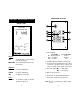
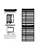
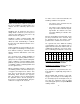
REAR PANEL HI 932700
1. Power Supply
15-24 VDC: 115 or 220 VAC:
P1 ! Not Connected Earth
P2 ! Negative Neutral
P3 ! Positive Live
2. Oxidant/Reductant dosage selection (see
page 10);
3. Connections for dosing pump to dose ei-
ther oxidant or reductant products. These
contacts act only as a switch for the power
to the drive;
4. Recorder output (M1 ! + mA output,
M2 ! - mA output);
5. BNC for ORP electrode;
6. Connection for Potential Matching Pin;
7. Connection for Electrode Reference.
Note: Be sure your main line is protected by
a fuse.
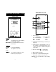
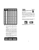
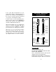
SET MEA
HI 932700
ORP CONTROLLER
SET
ON
SLOPE
SET
mV
FRONT PANEL
Keypad
SET To display and to set the working
point of ORP dosage
MEASURE To set HI 932700 to the measure-
ment mode
Trimmers
SLOPE For Slope Calibration
SET To adjust the Set Point
Leds
SET ON To show that oxidant or reduc-
tant dosage is in progress
FUNCTIONAL DESCRIPTION HI 932700