Instruction Manual HI 931700 HI 932700 Panel - Mounted pH - ORP Indicators Controllers http://www.hannainst.
Dear Customer, Thank you for chosing a Hanna Instruments Product. Please read this instruction manual carefully before using the instrument. This manual will provide you with all the necessary information for the correct use of the instrument, as well as a precise idea of its versatility in a wide range of applications. These instruments are in compliance with directives EN 50081-1 and 50082-1. TABLE OF CONTENTS Preliminary Examination ............................ 3 General Description .....................
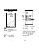
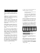
FUNCTIONAL DESCRIPTION HI 931700 REAR PANEL HI 931700 FRONT PANEL HI 931700 pH CONTROLLER pH SET ON OFFSET SLOPE SET SET MEA Keypad SET To display and to set the working point of pH dosage MEASURE To set HI 931700 to the measurement mode Trimmers 1. Power Supply 15-24 VDC: 115 or 220 VAC: P1 !Not Connected Earth P2 ! Negative Neutral P3 ! Positive Live 2. Acid/Base Dosage Selection (see page 10); 3. Connections for dosing pump to dose either acid or base products.
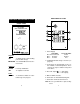
FUNCTIONAL DESCRIPTION HI 932700 REAR PANEL HI 932700 FRONT PANEL HI 932700 ORP CONTROLLER mV SET ON SLOPE SET SET MEA Keypad SET To display and to set the working point of ORP dosage MEASURE To set HI 932700 to the measurement mode Trimmers SLOPE SET For Slope Calibration To adjust the Set Point Leds SET ON To show that oxidant or reductant dosage is in progress 1. Power Supply 15-24 VDC: P1 ! Not Connected P2 ! Negative P3 ! Positive 115 or 220 VAC: Earth Neutral Live 2.
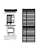
SPECIFICATIONS HI 931700 MECHANICAL DIMENSIONS HI 931700 Front view of the panel-mounted unit. Dimensions show the cutout size for the installation and also the outside dimensions of the panel. Range 0.00 to 14.00 pH Resolution 0.01 pH Accuracy ±0.02 pH Typical EMC Deviation ±0.02 pH Installation Cat. II 1012 Ohm Input Calibration 73mm 2.87" 79mm 3.11" Readout Recorder Output Set Point Relay Power Supply 42mm 1.65" 49mm 1.93" Environment Side view of the panel-mounted unit. 0.25/4mm 0.
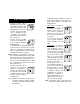
• INITIAL PREPARATION • Connect a 3-wire (115 or 230VAC versions) or 2-wire (15-24VDC version) power cable to the terminal strip paying attention to the correct live, earth and neutral (115 or 230VAC version) or positive and negative (15-24VDC version) terminal connections. • Connect the pH or ORP electrode to the BNC connector marked "INPUT ELECTRODE".
OPERATIONAL GUIDE CALIBRATION The setting of the various parameters are made via the front panel keys and trimmers. When each key is pressed the LED is lighted indicating to the user that the function is in operation. Make sure the meter is in the measurement mode (MEASURE LED light is on) before starting the calibration procedure. Make sure that the meters and electrodes are calibrated before operating the instruments (see page 13). To set the working point of pH or ORP dosage, press the "SET" key.
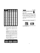
Temperature Buffer Buffer Buffer Buffer Buffer °C °F pH 4.01 pH 6.86 pH 7.01 pH 9.18 pH 10.01 0 5 10 15 20 25 30 35 40 45 50 55 60 65 70 75 80 85 90 95 32 41 50 59 68 77 86 95 104 113 122 131 140 149 158 167 176 185 194 203 4.01 4.00 4.00 4.00 4.00 4.01 4.02 4.03 4.04 4.05 4.06 4.07 4.09 4.11 4.12 4.14 4.16 4.17 4.19 4.20 6.98 6.95 6.92 6.90 6.88 6.86 6.85 6.84 6.84 6.83 6.83 6.84 6.84 6.85 6.85 6.86 6.86 6.87 6.88 6.89 7.13 7.10 7.07 7.04 7.03 7.01 7.00 6.99 6.98 6.98 6.98 6.98 6.98 6.99 6.99 7.00 7.
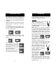
TAKING REDOX MEASUREMENTS To make correct redox measurements the following conditions must prevail: Redox measurements allow the quantification of the oxidizing or reducing power of a solution, and are commonly expressed in mV. Oxidation may be defined as the process during which a molecule (or an ion) loses electrons and reduction as the process by which electrons are gained.
In the event that measurements are performed with solutions containing sulfides or proteins, the cleaning of the diaphragm of the reference electrode must be performed (see page 21, "Cleaning Procedure"). In order to have a correct functioning of the ORP electrode, immerse it into HI 7020 and measure the response; the obtained value should be within 200 and 275 mV.
cannot function properly under these conditions. These bubbles can be removed by "shaking down" the electrode as you would do with a glass thermometer. If the bulb and/or junction are dry, soak the electrode in HI70300 Storage Solution for at least one hour. For refillable electrodes: If the fill solution (electrolyte) is more than 1 cm (½") below the fill hole, add HI 7082 3,5M KCl Electrolyte Solution for double junction or HI 7071 3,5M KCl+AgCl Electrolyte Solution for single junction electrodes.
IMPORTANT: After performing any of the cleaning procedures rinse the electrode thoroughly with distilled water, drain and refill the reference chamber with fresh electrolyte, (not necessary for GEL filled electrodes) and soak the electrode in HI 70300 Storage Solution for at least 1 hour before taking measurements. ter and then follow the Cleaning Procedure above.
TEMPERATURE-RESISTANCE CORRELATION FOR HANNA pH SENSITIVE GLASS The resistance of glass electrodes partially depends on the temperature. The lower the temperature, the higher the resistance. It takes longer time for the reading to stabilize if the resistance is higher. In addition, the response time will suffer to a greater degree at temperatures below 10°C.
SUGGESTED INSTALLATIONS SHORT DISTANCE, INDOOR INSTALLATION Due to the high impedance of the pH and ORP electrode's glass membrane (usually more than 100 MΩ), a very high grade of insulation is required. A dry environment is needed in order to obtain a level of insulation not lower than 1012 Ω.
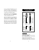
ACCESSORIES pH ELECTRODES HI 1090T pH CALIBRATION SOLUTIONS HI 7004M pH 4.01 Buffer Solution, 230 mL HI 7004L pH 4.01 Buffer Solution, 460 mL HI 7006M pH 6.86 Buffer Solution, 230 mL HI 7006L pH 6.86 Buffer Solution, 460 mL HI 7007M pH 7.01 Buffer Solution, 230 mL HI 7007L pH 7.01 Buffer Solution, 460 mL HI 7009M pH 9.18 Buffer Solution, 230 mL HI 7009L pH 9.18 Buffer Solution, 460 mL HI 7010M pH 10.01 Buffer Solution, 230 mL HI 7010L pH 10.
HI 1210T Screw cap PG13.5 connector, double junction, plastic-body PG13.5 THREAD φ 12mm HI 2910B/5 BNC connector, 5 m (16.5') cable, double junction, plastic-body, built-in amplifier 3/4 x 16 UNF DIA 12mm DIA 20.5mm 30mm HI 1910B 38.5mm 110mm BNC connector, 1 m (3.3') cable, double junction, plastic-body, built-in amplifier 3/4 x 16 UNF DIA 12mm ORP ELECTRODES HI 2930B/5 BNC connector, 5 m (16.5') cable, Pt, Ultem®-body, built-in amplifier 3/4 x 16 UNF DIA 20.5mm 38.
HI 3210T Screw cap PG13.5 connector, Pt, plastic-body PG13.5 THREAD φ 12mm EXTENSION CABLES FOR SCREW-TYPE ELECTRODES ONLY (SCREW TO BNC CONNECTOR) HI 7855 SERIES CABLE CONNECTORS CONNECTOR AND 3.0 mm (0.12") CABLE WITH BNC 30mm HI 3410S Screw connector, Pt, plastic-body HI 3430B/3 BNC connector, 3 m (9.9') cable, Pt, plastic-body 3/4 x 16 UNF M13 x 1.5 DIA 16 mm DIA 12mm DIA 20.5mm 25 7 mm mm 38.5mm HI 3410S HI 3932B/5 BNC connector, 5 m (16.
WARRANTY CE DECLARATION OF CONFORMITY All Hanna Instruments meters are warranted for two years against defects in workmanship and materials when used for their intended purpose and maintained according to instructions. The probes and the electrodes are warranted for a period of six months. Damages due to accident, misuse, tampering or lack of prescribed maintenance are not covered. This warranty is limited to repair or replacement free of charge.
h t t p : / / w w w . h a n n a i n s t .