Instruction Manual HI 8931A/B/C/D HI 8936A/B/C/D HI 8936AL/BL/CL/DL HI 943500A/B/C/D Conductivity Process Instrumentation These Instruments are in Compliance with the CE Directives
Dear Customer, Thank you for choosing a Hanna Instruments Product. Please read this instruction manual carefully before using the instrument. This manual will provide you with all the necessary information for correct use of the instruments, as well as a precise idea of thier versatility in a wide range of applications. directives. These instruments are in compliance with the TABLE OF CONTENTS Preliminary Examination ............................................................ 3 General Description .......
PRELIMINARY EXAMINATION Remove the instrument from the packing material and examine it carefully to make sure that no damage has occurred during shipping. If there is any noticeable damage, notify your Dealer. Note: Save all packing materials until you are sure that the instrument functions correctly. All defective items must be returned in the original packing materials together with the supplied accessories.
Four models with different measurement ranges are available to suit individual applications: HI 8931A / HI 943500A HI 8936A / HI 8936AL from 0.0 to 199.9 mS/cm HI 8931B / HI 943500B HI 8936B / HI 8936BL from 0.00 to 19.99 mS/cm HI 8931C / HI 943500C HI 8936C / HI 8936CL from 0 to 1999 µS/cm HI 8931D / HI 943500D HI 8936D / HI 8936DL from 0.0 to 199.
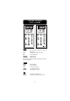
FUNCTIONAL DESCRIPTION HI 8931 & HI 943500 KEYPAD MEASURE To read the measurement values and to enable the diagnostic tests ∆AL To display the set tolerance of the alarm SET To set the working point TEST SLOPE Diagnostic function TESTOFFSET Diagnostic function When each key is pressed the LED is lighted indicating to the user that the function is in operation.
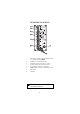
THE REAR PANEL OF HI 8931A/B/C/D 1. 2. 3. 4. 5. 6. 7. 8. Power OUTPUT Terminals (+20V and COM) for connection to a conductivity transmitter HI8936 mA INPUT from a conductivity transmitter mA OUTPUT Terminals for connection to a recorder SET SELECT Terminals for reverse control operation SET Terminals for connection to a dosing pump ALARM Terminals for connection to an external alarm device Power Supply Fuse Holder. Unplug the instrument from power supply before the replacement of the fuse.
THE REAR PANEL OF HI 943500A/B/C/D 1. 2. 3. 4. 5. 6. 7. Conductivity Probe Connector (7-pin DIN) mA OUTPUT Terminals for connection to a recorder SET SELECT Terminals for reverse control operation SET Terminals for connection to a dosing pump ALARM Terminals for connection to an external alarm device Power Supply Fuse Holder. Unplug the instrument from power supply before the replacement of the fuse.
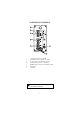
MECHANICAL DIMENSIONS OF HI 8931 AND HI 943500 Front view of the panel-mounted unit 141mm 5.55" 144mm 5.67" 69mm 2.71" 72mm 2.83" These dimensions show the cutout size for the installation. Side view of the panel-mounted unit 0.25/4mm 0.01/0.160" ADJUSTABLE LOCATION BRACKET 144mm 5.67" 135mm 5.31" 190mm MIN 7.50" Adjustable location brackets (supplied with the meter) allow the indicator to slide into the cutout and will hold the unit securely in place. 190 mm (7.
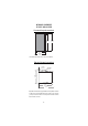
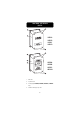
FUNCTIONAL DESCRIPTION HI 8936 HI8936A HI8936B HI8936C HI8936D HI8936AL HI8936BL HI8936CL HI8936DL 1. Back Cover 2. Top Plastic Cover 3. LCD Display (for HI 8936AL, HI 8936BL, HI 8936CL, HI 8936DL only) 4. Screws for fastening the top cover.
SIDE VIEW HI 8936A HI8936B HI8936C HI8936D HI 8936AL HI8936BL HI8936CL HI8936DL 1. Top Plastic Cover 2. Wire cable glands.
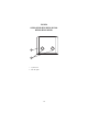
MECHANICAL DIMENSIONS HI 8936A, HI8936B, HI 8936C, HI 8936D HI 8614 165mm 6.50" 90mm 3.54" 4 x 4.3mm 4 x 0.17" 100mm 3.94" 110mm 4.33" 155mm 6.10" MECHANICAL DIMENSIONS HI 8936AL, HI8936BL, HI 8936CL, HI 8936DL 165mm 6.50" 58mm 2.28" 126mm 5.00" 24mm 0.94" 90mm 3.54" HI 8614L 45mm 1.77" 4 x 4.3mm 4 x 0.17" 155mm 6.10" 11 100mm 3.94" 110mm 4.
CONDUCTIVITY PROBES HI 7635 In-line Conductivity Probe HI 7635 is a one piece, molded conductivity probe with pipe threads (1" NPT) at both ends. This allows the probe to attach to an in-line system, and to be used in conjunction with the HI 8936 conductivity transmitter. The HI 7635 uses a 4-ring potentiometric measuring method. This method is highly accurate and requires very little maintenance. The construction of the housing is rugged, fiber-reinforced polypropylene.
HI7638 Tank Conductivity Probe HI 7638 conductivity probe combines the proven 4-ring potentiometric method of measuring conductivity with the platinum sensor and stainless steel external thread. This method incorporates a series of four platinum rings into the probe shaft and is highly accurate requiring very little maintenance. ® The removable cover is made of Ultem which resists the harmful effect of most chemicals and can be unscrewed for quick and simple maintenance.
SPECIFICATIONS HI 8931 & HI 943500 Range HI8931A - HI943500A HI8931B - HI943500B HI8931C - HI943500C HI8931D - HI943500D Accuracy (@20°C/68°F) Typical EMC Deviation 4-20mA INPUT from Transmitter HI8931A HI8931B HI8931C HI8931D HI943500 Conductivity Probe Calibration Temp. Compensation HI8931 HI943500 Readout Recorder Output 1 Set Point Relay & 1 Alarm Relay Power Supply Panel Cutout Environment Weight Enclosure 0.0 to 199.9 mS/cm 0.00 to 19.99 mS/cm 0 to 1999 µS/cm 0.0 to 199.
SPECIFICATIONS HI 8936 & HI 8936L Range HI8936A & AL HI8936B & BL HI8936C & CL HI8936D & DL Accuracy (@20°C/68°F) Typical EMC Deviation Conductivity Probe Calibration Temperature Compensation Output Power Supply HI8936A/B/C/D HI8936AL/BL/CL/DL Protection Environment Dimensions Weight 0.0 to 199.9 mS/cm 0.00 to 19.99 mS/cm 0 to 1999 µS/cm 0.0 to 199.9 µS/cm ±2% of Full Scale excluding probe error ±2% of Full Scale ±0.
CONNECTIONS REAR CONNECTIONS FOR HI 8931 • Power Connection Terminals 4-screw-terminal-strip for connection to a 3-wire power cable according to the indicated voltage (115 or 230V). • IN/OUT Transmitter 2 wires of the 4-core signal cable from the conductivity transmitter (HI8936) have to be connected to the mA input terminals and the other 2 wires to the "+20V" and "COM" while paying careful attention to the polarity.
• Set Select These contacts permit the activation of a Set Contact relay when the measured value is lower (connected terminals) or higher (open terminals) than the user's set value. See also page 27. • +4-20 mA These are the output terminals for connection to a recorder or other control equipment. The output current varies from 4 to 20 mA and is proportional to the measured conductivity value. • Alarm Contacts During normal operation these terminals remain closed.
TERMINAL BOARD CONNECTIONS FOR H8936 • Remove the 4 screws and the top cover of the HI 8936 conductivity transmitter to obtain access to the terminal board connections.
HI8931 conductivity controller (see also page 24). The 4-core cable has to be connected to the transmitter according to the label instructions on the 4terminal strip. The regulated D.C. supply required for the proper operation of the transmitter is "+20V", labeled "+20V" and "COM". The current (mA) output terminals are labeled "4-20 mA" and "COM". The transmitter is protected against inversion of supply voltage. • HI8936 used in conjunction with an external power supply Use 2 PVC insulated 2-core cables.
• Probe Connection The conductivity probe is supplied with a 3 m (10'), 6 core cable. The cable is to be connected to the terminals provided (see also page 23 for proper connection scheme of HI 7635 and HI 7638).
REAR CONNECTIONS FOR HI 943500 • Power Connection Terminals 4-screw-terminal-strip for connection to a 3-wire power cable according to the indicated voltage (115 or 230V). • 7-pin DIN connector socket For connection to the HI 7638 conductivity probe. • + mA output The first and the second terminals are the output terminals for connection to a recorder or other control equipment. The output current varies from 4 to 20 mA and is proportional to the measured conductivity value.
• Set Dosing pumps or other control equipment may be connected to the "SET" (Max. 2A, 240V) terminals. These contacts act only as a "dry" switch allowing electrical continuity, not as a power supply. • Alarm Contacts During normal operation these terminals remain closed. If the measured conductivity level is not within the tolerance of the set value, the alarm contact is open. These contacts act only as a switch. See also page 28.
CONDUCTIVITY PROBE CONNECTIONS The connections for HI 7635 are color coded for easy installation and are as follows: HI 7635 cable HI 8936 transmitter Black or Grey Red or Pink Brown or Orange Blue White Green or Yellow NTC SENSOR probe pin 1 probe pin 2 probe pin 3 probe pin 4 The connections for HI 7638 are as follows: HI 7638 #1 #2 #3 #4 #5 #6 HI8936 transmitter probe pin 1 probe pin 2 probe pin 3 probe pin 4 NTC SENSOR connector inside view Note: NTC and SENSOR are equivalent and are both label
OPERATIONAL GUIDE INITIAL PREPARATION & INSTALLATION: Material needed: • a 3-wire power cable (for connection of HI 8931/HI 943500 to the mains) • a PVC insulated 4-core cable (as connection cable between HI 8931 and HI8936) • rubber seals and a pipe sealant (for installation of HI7635) FOR HI 8931 AND HI 8936 ONLY • Remove the 4 screws and the top of the HI8936 Process Conductivity transmitter.
• The HI 8936 transmitter may be wallmounted at any convenient location close to the measurement site. To minimize thermal drifts due to extreme temperature fluctuations, particularly if the measurement is conducted outdoors, it is recommended that the transmitter is protected in a casing. • For the installation of the HI 7635 conductivity probe, it is necessary to use rubber seals between the probe and the pipe or elbow joints. A pipe sealant is also recommended to ensure a leak free joint.
• It is recommended that the HI 7635 is installed vertically. This is to ensure that trapped air bubbles or turbulent flows cause minimal interference to the measurement system. The maximum working pressure of this unit is 5 BAR (72.5 psi). CAUTION: do not use in systems where temperature exceeds 80°C (176°F). • The HI7638 process conductivity probe is also supplied with a 3 m (10') length cable. The six core cable from this probe is connected to the HI 8936 process conductivity transmitter as shown.
OPERATING INFORMATION The various parameters are set through the front panel keys and trimmers. When each key is pressed the corresponding LED is lit, indicating that the function is operational. Make sure that the conductivity meter, transmitter and probe are calibrated before using the instrument for measurements (see page 30 & 34 for HI 8931 & HI 8936 and page 38 for HI 943500). SET POINT To set the working point of the controller, press the SET key. The display will indicate the set value.
Below set-point control operation Short the SET SELECT/COM connectors with a jumper wire. The set contact relay will close if the measured value is lower than the set-point value and the SET ON LED will be lit. COM SET SELECT ALARM Press the ∆AL key and the display will show the set tolerance for the alarm. Use a small screwdriver to adjust the trimmer ∆AL until the desired tolerance is displayed.
When the alarm is active the ALARM LED is lit. The alarm contacts of HI 8931 and HI 943500 remain closed during normal operation. If the measured conductivity level is not within the tolerance of the set value, the alarm contact will be open. TAKING MEASUREMENTS WITH HI 8931 AND HI 943500 After setting the working point and alarm value, press the MEASURE key. The actual conductivity value of the test solution will be displayed.
CALIBRATION PROCEDURE OF HI8931 & HI8936 WITH HI7635 Material needed • HI 7635 conductivity probe • HI 8931 conductivity controller • HI 8936 conductivity transmitter • A 20 mA f.s. ammeter (for transmitters without LCD) • A reference conductivity meter with automatic temperature compensation accurately calibrated (e.g. HI 8733). PROCEDURE • Connect the HI 7635 probe to the HI 8936 transmitter (see page 23). • Connect the HI 8936 transmitter to the HI 8931 controller (see page 24).
• Ensure that there is no solution inside the HI 7635 conductivity probe (dry probe). • When the power is on, the ammeter should read "4.0 mA". The HI 8936L transmitter with LCD should display "0". • If not, adjust the OFFSET trimmer of the HI 8936 transmitter to obtain "4 mA" or "0" on the HI 8936L. • The HI 8931 controller should display "0" value. • If not, adjust the OFFSET trimmer of HI 8931 to display a zero reading.
• The reading will be converted to mA by the following formula: mA = K (measured value x 16/2000) + 4 K = conversion factor depending on the model Model HI 8936A & AL HI 8936B & BL HI8936C & CL HI8936D & DL Conversion factor K 10 100 1 10 For example, using a HI 8936A, if the measured value is 123.4 mS, then output current = 10 x (123.4 x 16/2000) + 4 = 13.9 mA Adjust the SLOPE trimmer of the HI 8936 transmitter to read "13.
• The calibration is now complete and the instrument is ready for use. All subsequent measurements will now be compensated to 25°C (77°F). • If the instrument will not calibrate refer to the Probe Maintenance and Cleaning section (see page 46). • If the HI 8936 transmitter is not used in conjunction with the HI 8931 controller, connect the transmitter to an external power supply (see page 19). Connect the transmitter to the HI 7635 conductivity probe (see page 23) and to an ammeter (see page 19).
CALIBRATION PROCEDURE OF HI8931 & HI8936 WITH HI7638 Material needed • HI 7638 conductivity probe • HI 8931 conductivity controller • HI 8936 conductivity transmitter • An ammeter (for transmitters without LCD) • Calibration solutions, according to the different models: HI7034 80 mS/cm @25°C for HI 8931A, HI 8936A & AL HI7030 12.
• Leave the HI 7638 conductivity probe in air (dry probe). • When the power is on, the ammeter should read "4.0 mA" or the HI 8936L transmitter with LCD should display "0". • If not adjust the OFFSET trimmer of the HI 8936 transmitter to obtain "4 mA" or "0" on the HI 8936L. • The HI 8931 controller should display "0" value. • If not adjust the OFFSET trimmer of HI 8931 to display a zero reading.
0 703 HI 8 cm (3¼") • Pour enough conductivity solution into a plastic beaker to achieve at least 8 cm (3¼") of depth. • Immerse the probe into the beaker with the conductivity solution. The holes on the sleeve must be completely submerged in the solution. • Tap the probe repeatedly on the bottom of the beaker and stir it to ensure that no air bubbles are trapped inside the sleeve.
• FOR HI 8931 When the reading stabilizes, turn the SLOPE trimmer on the front of the HI 8931 until the LCD reading is the same as the calibration solution at 25°C (77°F), i.e. "80.0 mS" using HI 7034 with HI 8931A "12.88 mS" using HI 7030 with HI 8931B "1413 µS" using HI 7031 with HI 8931C "84.0 µS" using HI 7033 with HI 8931D • The calibration is now complete and the instrument is ready for use. All subsequent measurements will now be compensated to 25°C (77°F).
CALIBRATION PROCEDURE OF HI943500 WITH HI7638 Material needed • HI7638 conductivity probe • HI943500 conductivity controller • Calibration solutions, according to the different models: HI7034 80mS/cm @25°C for HI943500A HI7030 12.88 mS/cm@25°C for HI943500B HI7031 1413 µS/cm @25°C for HI943500C HI7033 84 µS/cm @25°C for HI943500D PROCEDURE • Ensure that the probe is connected to the meter securely by aligning the pins with the socket, pushing the plug in and tightening the threaded ring.
HI 703 0 • Adjust the OFFSET trimmer if the LCD does not show the zero reading. 8 cm (3¼") • Pour enough conductivity solution into a beaker to achieve at least 8 cm (3¼") of depth. • Immerse the probe into the beaker with the conductivity solution. The holes on the sleeve must be completely submerged in the solution. • Tap the probe repeatedly on the bottom of the beaker and stir it to ensure that no air bubbles are trapped inside the sleeve.
• The calibration is now complete and the instrument is ready for use. All subsequent measurements will now be compensated to 25°C (77°F). • If the instrument will not calibrate refer to the Probe Maintenance and Cleaning section (see page 46).
CONDUCTIVITY VERSUS TEMPERATURE CHART °C °F HI7030 HI7031 HI 7033 HI 7034 HI7035 HI7039 (mS/cm) (mS/cm) (mS/cm) (mS/cm) (mS/cm) (mS/cm) 0 32 7150 776 64 48300 65400 2760 5 41 8220 896 65 53500 74100 3180 10 50 9330 1020 67 59600 83200 3615 15 59 10480 1147 68 65400 92500 4063 16 60.8 10720 1173 70 67200 94400 4155 17 62.6 10950 1199 71 68500 96300 4245 18 64.4 11190 1225 73 69800 98200 4337 19 66.
DIAGNOSTIC TESTS The HI 8931 and HI 943500 controllers are designed with built-in diagnostic functions to enable the user to check and troubleshoot the instrument. The checks performed are through the front panel keys and can be used to isolate the cause of malfunction. Press the MEASURE key before proceeding the following tests. A) Test Offset Press the TEST OFFSET key and the display should indicate the following values: HI 8931/HI 943500A HI 8931/HI 943500B HI 8931/HI 943500C HI 8931/HI 943500D 0.
B) Test Slope Press the TEST SLOPE key and the display should indicate the following values: HI 8931/HI 943500A HI 8931/HI 943500B HI 8931/HI 943500C HI 8931/HI 943500D 100.0 mS 10.00 mS 1000 µS 100.0 µS ±35.0 mS ±3.50 mS ±350 µS ±35.0 µS Note: The reading obtained by these functions will vary if the OFFSET and the SLOPE trimmers on the front panel are adjusted.
INSTALLATION EXAMPLES Some typical installation setups are depicted in the following examples: Example #1 Example #2 44
Example #3 Example #4 Example #5 45
PROBE MAINTENANCE & CLEANING The probe can be compensated for normal contamination by a process of re-calibration. However, it is recommended that the process conductivity probe be removed from the system regularly for maintenance. For HI 7635 only: Deposits on the conductivity probe can be removed by immersing the probe in 0.1 N Hydrochloric acid for about 30 minutes. Heavier deposits may demand longer immersion periods. Clean the electrode thoroughly with water prior to the reinstallation.
ACCESSORIES CONDUCTIVITY BUFFER SOLUTIONS HI 7030L 12880 µS/cm (µmho/cm) @25°C (77°F), 460 mL HI 7030M 12880 µS/cm (µmho/cm) @25°C (77°F), 230 mL HI 7031L 1413 µS/cm (µmho/cm) @25°C (77°F), 460 mL HI 7031M 1413 µS/cm (µmho/cm) @25°C (77°F), 230 mL HI 7033L 84 µS/cm (µmho/cm) @25°C (77°F), 460 mL HI 7033M 84 µS/cm (µmho/cm) @25°C (77°F), 230 mL HI 7034L 80000 µS/cm (µmho/cm) @25°C (77°F), 460 mL HI 7034M 80000 µS/cm (µmho/cm) @25°C (77°F), 230 mL HI 7035L 111800 µS/cm (µmho/cm) @25°C (77°F),
CONDUCTIVITY PROBES HI7635 In-line conductivity probe, 3 m (10') cable (for HI 8936 only) 142mm 5.60" 52mm 2.04" 73mm 2.
OTHER ACCESSORIES HI 731326 Small calibration screwdrivers (20 pcs) HI 779/P 6-wire cable (100 m/330' roll) HI 8733 Portable conductivity meter with automatic temperature compensation 49
WARRANTY All Hanna Instruments meters are warranted for two years against defects in workmanship and materials when used for their intended purpose and maintained according to instructions. The probes are warranted for a period of six months. This warranty is limited to repair or replacement free of charge. Damages due to accident, misuse, tampering or lack of prescribed maintenance are not covered. If service is required, contact the dealer from whom you purchased the instrument.
CE DECLARATION OF CONFORMITY Recommendations for Users Before using these products, make sure that they are entirely suitable for the environment in which they are used. Operation of these instruments in residential area could cause unacceptable interferences to radio and TV equipments, requiring the operator to take all necessary steps to correct interferences. The trimmers are sensitive to electrostatic discharges. It is recommended to use antistatic screwdrivers.
MANCDPRCR4 05/03 w w w . h a n n a i n s t .