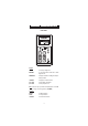
Instruction Manual HI 8510 • HI 8512 HI 8710 • HI 8711 HI 8720 Panel Mounted pH and ORP Indicators and Controllers w w w. h a n n a i n s t .
Dear Customer, Thank you for choosing a Hanna Instruments product. Please read this instruction manual carefully before using these instruments. This manual will provide you with the necessary information for correct use of these instruments, as well as a precise idea of their versatility. If you need additional technical information, do not hesitate to e-mail us at tech@hannainst.com or view our worldwide contact list at www.hannainst.com.
PRELIMINARY EXAMINATION Remove the instrument from the packing material and examine it carefully to make sure that no damage has occurred during shipping. If there is any noticeable damage, immediately notify your dealer. Each model is supplied with: • Transparent Splash-proof Front Cover • Mounting Brackets • Instruction Manual Note: Save all packing materials until you are sure that the instrument functions correctly.
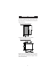
MECHANICAL DIMENSIONS The meters are provided with a black anodized aluminum body, front and back panels in shockproof ABS plastic and a transparent splash-proof front cover. Front view of the panel-mounted unit The dimensions show the cutout size for the installation. Side view of the panel-mounted unit Adjustable location brackets (supplied with the meter) allow the indicator to slide into the cutout and will hold the unit securely in place. 190 mm (7.
FUNCTIONAL DESCRIPTION HI 8510 FRONT PANEL Keypad SENSOR TEST pH 7 TEST pH 4 TEST To display the mV reading of the electrode and, therefore, verify its working condition To verify the internal circuit of the meter in terms of Offset compensation To verify the amplifier circuit of the meter Note: Each time a key is pressed the corresponding LED is turned ON.
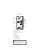
REAR PANEL HI 8510 1. 2. 3. 4. 5. 6. 7. 8. 9. 10. BNC socket for pH electrode Input from amplified electrode Connections for Pt100 temperature sensor Power supply terminals Fuse holder Recorder output terminals Connection to the transmiter Power for amplified electrode Connection for matching pin Connection for reference electrode Unplug the instrument from the power supply before replacing the fuse. Only one of BNC, AMP INPUT or INPUT TRANSMITTER connectors can be used at a moment.
FUNCTIONAL DESCRIPTION HI 8512 FRONT PANEL Keypad 0 mV TEST 1000 mV TEST To verify the instrument calibration at 0 mV To verify the slope at 1000 mV Note: Each time a key is pressed the corresponding LED is turned ON.
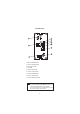
REAR PANEL HI 8512 1. BNC socket for ORP electrode 2. Input from amplified electrode 3. Power supply terminals 4. Fuse holder 5. Recorder output terminals 6. Connection to the transmitter 7. Power for amplified electrode 8. Connection for matching pin 9. Connection for reference electrode Unplug the instrument from the power supply before replacing the fuse. Only one of BNC, AMP INPUT or INPUT TRANSMITTER connectors can be used at a moment. Leave the other two inputs unconnected.
FUNCTIONAL DESCRIPTION HI 8710 FRONT PANEL Keypad SET MEASURE SENSOR TEST ΔALARM pH 7 TEST pH 4 TEST To set the pH dosage limit To enter measurement mode and to enable diagnostic tests To display electrode mV reading and verify its working condition To display & set alarm tolerance To verify Offset compensation To verify amplifier circuit Note: Each time a key is pressed the corresponding LED is turned ON or changes its blinking behavior (ΔALARM).
SET/COARSE SET/FINE To coarsely adjust the setpoint To finely adjust the setpoint LEDs ACID (blinking) Shows that acid dosage is active ALK. (blinking) Shows that alkaline dosage is active ΔALARM (blinking) Indicates an active alarm DOSAGE MODE SWITCH Blinks when the dosing switch is in OFF or ON position.
REAR PANEL HI 8710 1. 2. 3. 4. 5. 6. 7. 8. 9. 10. 11. 12. 13. 14. 15. 16.
FUNCTIONAL DESCRIPTION HI 8711 FRONT PANEL Keypad ALK.
Trimmers SLOPE OFFSET ΔALARM ALK. SET COARSE FINE For Slope calibration For Offset calibration To set the tolerance of the alarm To coarsely adjust alkaline setpoint To finely adjust alkaline setpoint ACID SET COARSE FINE To coarsely adjust acid setpoint To finely adjust acid setpoint LEDs ALK. SET (Blinking) ACID SET (Blinking) (Blinking) ΔALARM ALK.
REAR PANEL HI 8711 1. 2. 3. 4. 5. 6. 7. 8. 9. 10. 11. 12. 13. 14. 15.
FUNCTIONAL DESCRIPTION HI 8720 FRONT PANEL Keypad SET MEASURE ΔALARM 0 mV TEST 1000 mV TEST To set the working point of ORP dosage To enter measurement mode and to enable diagnostic tests To display and set the alarm tolerance To verify the instrument calibration at 0 mV To verify the slope at 1000mV Note: Each time a key is pressed the corresponding LED is turned ON or changes its blinking behavior (ΔALARM).
Trimmers CAL ΔALARM SET/COARSE SET/FINE LEDs OXID (Blinking) RED. (Blinking) ΔALARM (Blinking) DOSAGE MODE SWITCH For ORP calibration To display and set the alarm tolerance To coarsely adjust the setpoint To finely adjust the setpoint Show that the oxidant dosage is active Show that the reductant dosage is active Indicate an active alarm Blinks when the dosage switch is in OFF or ON position.
REAR PANEL HI 8720 1. 2. 3. 4. 5. 6. 7. 8. 9. 10. 11. 12. 13. 14. 15. BNC socket for ORP electrode Input from amplified electrode Oxid/Reduc dosage consent terminals Connections for dosing pump Alarm contacts Power supply terminals Fuse holder OXID/RED.
SPECIFICATIONS HI 8510 I N PU T Electrode Transmitter 0.00 to 14.00 pH RANGE 0.01 pH RESOLUTION ACCURACY (@20 °C/68 °F) INPUTS ±0.02 pH (0 to 100 °C) ±0.05 pH (-20 to 0 °C) High impedance 1012 Ohm; Reference and Matching pin inputs are a va ila b le ±0.
HI 8710 I N PU T Elect rode Transmit t er 0.00 to 14.00 pH RANGE 0.01 pH RESOLUTION ACCURACY (@20 °C/68 °C) INPUTS ±0.02 pH (0 to 100 °C) ±0.05 pH (-20 to 0 °C) High impedance 1012 Ohm; Reference and Matching Pin inputs are a va ila b le ±0.
DOSING CONTROL OFF/AUTO/ON with selection switch OVER DOSING CONTROL Adjustable, from 5 min to 60 min with knob or Disable by wire strap - on rear panel BACKLIGHT Continuous ON POWER SUPPLY 115 or 230 Vac; 60/50 Hz ENCLOSURE ENVIRONMENT Black anodized aluminium body; front and back with ABS; transparent splash-proof front cover -10 to 50 °C (14 to 122 °F); RH max 95% non condensing PANEL CUTOUT 141 x 69 mm (5.6 x 2.7'') WEIGHT 1 kg (2.2 lb.
INITIAL PREPARATION • Connect a 3-wire cable to the power supply terminal according to the voltage level as indicated, and pay particular attention to the correct line, earth and neutral connections. • For BNC electrodes, connect the electrode to the BNC plug on the rear panel. The instruments are equiped with differential input. To benefit from differential input advantages, connect the proper electrode wire (if available) or a cable with a potential matching pin, to the Matching Pin (terminal 4).
Connect the “+” wire of the recorder to the terminal 1 on the instrument and the other wire (common) to terminal 2 for 4-20 mA recorder output or to terminal 3 for 0-20 mA recorder output. Note: Only one recorder output connection is possible. In order to avoid malfunction leave the unused terminal unconnected. • Pt100 terminals: these contacts are used to connect the Pt100 temperature sensor for automatic temperature compensation of pH readings.
• ALK. contact (HI 8711) (see picture, terminals 3 and 4): these contacts are used to connect the dosing pump for base, and act as a switch for the power to the drive. • CONSENT contacts (HI 8710 and HI 8720, see picture, terminals 3 and 4): these contacts (max. 2A, 240V) are used for reduction and oxidation reactions when the pH controller works in conjunction with an ORP controller and vice versa.
OPERATIONAL GUIDE All instrument settings are made via front panel keys and trimmers. When a key is pressed, the corresponding LED lights up to show the operating function. If the LED blinks before pressing the key, it will change the blinking style. If using an asigned electrode, make sure that the meter is calibrated before starting any operation (see "Calibration" section for details). Be sure that the dosage switch is in AUTO position.
Using a small screwdriver adjust the COARSE and FINE trimmers to display the desired set value. SET POINTS (HI 8711) To set the working point for alkaline dosage, press the ALK. SET key and the display will show the set value for alkaline dosage. The ALK. SET LED will turn ON if alkaline dosage is deactivated or change blinking style. Using a small screwdriver adjust the ALK. SET COARSE and FINE trimmers to display the desired base set value.
Note: The ALK. and the ACID setpoints can be set on the entire range 0.00 pH to 14.00 pH using COARSE and FINE trimmers. In order to avoid erroneous situations the ALK. setpoint value should not exceed the ACID setpoint value. ALARMS (HI 8710, HI 8711 and HI 8720) To set the alarm tolerance, press ΔALARM key and the display will show the current value. Using a small screwdriver adjust the ΔALARM trimmer to display the desired tolerance. Examples: For HI 8710, if the set value is pH 3 and the ΔALARM is 1.
The actual pH or ORP value of the test solution is displayed. When acid dosage is active, the ACID LED lights up, while during alkaline dosage, the ALK. LED turns on (HI 8710 only). When oxidant dosage is active, the OXID LED lights up, while during reductant dosage, the RED. LED turns on (HI 8720 only). When the dosage switch is in OFF or continuous ON position the corresponding LED blinks (the LED on the right side of the switch).
Two DOSAGE MODE switches are designed for HI8711, one for ACID and the other for ALK. channels. If for any reason one of them is in OFF position the corresponding dosing relay is deactivated. The alarm relay will be activated only in accordance with the other channel. The ALARM LED will work as in AUTO mode. p H CALIBRATION Make sure that the instrument is in measurement mode (MEASURE LED is on) before proceeding with calibration.
Rinse pH electrode and the reference thermometer thoroughly with pH 4.01 rinsing solution, then immerse them in pH 4.01 (HI 7004) or pH 10.01 (HI 7010) buffer solution. Note: For accurate readings, use pH 4.01 if you are going to measure acid samples or pH 10.01 for alkaline measurements. Shake briefly and wait one minute before adjusting the SLOPE trimmer to display the ph value of the buffer solution, i.e. pH 4.01 (or 10.01) at 25°C (77°F).
p H VALUES AT VARIOUS TEMPERATURE Temperature has an effect on the pH. The calibration buffer solutions are affected by temperature changes to a lesser degree than normal solutions. Please refer to the following chart to perform the pH calibration: TEMP pH BUFFERS ºC ºF 4. 01 6. 86 7. 01 9. 18 10. 01 0 32 4.01 6.98 7.13 9.46 10.32 5 41 4.00 6.95 7.10 9.39 10.24 10 50 4.00 6.92 7.07 9.33 10.18 15 59 4.00 6.90 7.05 9.27 10.12 20 68 4.00 6.88 7.03 9.22 10.06 25 77 4.
p H DIAGNOSTIC TESTS HI 8510, HI 8710 and HI 8711 are provided with autodiagnostic functions that allow to check and troubleshoot any malfunctioning. The functions are made via front panel keys to isolate the cause of malfunction whether it is due to pH electrode contamination, internal offset circuit or amplifier circuit. Follow the procedure described below. First press the MEASURE key, then one of the following keys. A) Sensor Test Immerse the electrode in pH 7.
C) Amplifier Circuit Test Press the pH 4 TEST key and the display should show a value within the 3.30 to 4.30 pH range, to verify the amplifier circuit of the meter. The corresponding LED turns on.
ORP DIAGNOSTIC TESTS HI 8512 and HI 8720 are ORP controllers provided with autodiagnostic functions that allow to check and troubleshoot any malfunctioning. The functions are made via front panel keys to isolate the cause of malfunction. For HI 8720 only, press MEASURE key before proceeding with the following tests. A) 0 mV Test Press the 0 mV TEST key and the display should show a value of 0±10 mV, to verify the "zero" calibration of the instrument. The corresponding LED turns on.
LED INDICATION All LEDs above the keys indicate the state of each function, whether it is active or the display is indicating the mode. For HI 8711 only Each LED can be in one of the following states: A) Light on The mode is displayed on the LCD but is not active, e.g. the alarm setpoint is displayed but the alarm contact is open. B) Light blinking 25% on, 75% off The mode is not displayed but it is active, e.g. the alarm contact is opened but the alarm setpoint is not displayed.
TAKING REDOX MEASUREMENTS Redox measurements allow the quantification of the solution oxidizing/ reducing power, and are commonly expressed in mV. Oxidation may be defined as the process during which a molecule (or an ion) loses electrons and reduction as the process by which electrons are gained. Oxidation is always coupled together with reduction, so that as one element gets oxidized, the other is automatically reduced, therefore the term oxidation-reduction is frequently used.
Oxidizing pre-treatment: immerse the electrode for some minutes in HI 7092 solution. If no pre-treatment is performed, the electrode will have long response times. If working with refillable electrodes, always check the internal electrolyte level and refillwith HI 7071 solution, if necessary (the level must be at least 2.5 cm below the filling hole).
ELECTRODE MAINTENENCE PREPARATION PROCEDURE Remove the protective cap. DO NOT BE ALARMED IF ANY SALT DEPOSITS ARE PRESENT. This is normal with electrodes and they will disappear when rinsed with water. During transport tiny air bubbles may form inside the glass bulb, and the electrode cannot function properly under these conditions. Remove the bubbles by "shaking down" the electrode as you would do with a glass thermometer.
For refillable electrodes: If the internal electrolyte solution is more than 1 cm (½") below the filling hole, add HI 7082 solution (3.5M KCl) for double junction electrodes or HI 7071 (3.5M KCl+AgCl) for single junction electrodes. For a faster response unscrew the filling hole screw during measurements. For AmpHel® electrodes: If the electrode does not respond to pH changes, the battery is run down and the electrode should be replaced. MEASUREMENT Rinse the electrode tip with distilled water.
CLEANING PROCEDURE • General Soak in HI 7061 general cleaning solution for approximately 1 hour. Removal of films, dirt or deposits on the membrane/junction: • Protein Soak in Hanna HI 7073 protein cleaning solution for 15 minutes. • Inorganic Soak in Hanna HI 7074 inorganic cleaning solution for 15 minutes. • Oil/grease Rinse with Hanna HI 7077 oil & fat cleaning solution.
SUGGESTED INSTALLATIONS SHORT DISTANCE, INDOOR INSTALLATION Due to the low current involved, a very high grade of insulation is required. A dry environment is needed in order to obtain a insulation level not lower than 1012 ohm. This type of connection is very delicate and requires constant attention to maintain proper operating conditions. Conventional electrodes should be used in indoor applications only, with a cable not longer than 10 m (33').
LONG DISTANCE INSTALLATIONS, ISOLATED OUTPUT FOR PC INTERFACE If the needed installation distance is greater than 50 m (165'), it is necessary the use of a transmitter. HANNA instruments® offers a full line of pH and ORP transmitters with or without display.
ACCESSORIES pH CALIBRATION SOLUTIONS HI 7004M pH 4.01 buffer solution, 230 mL HI 7004L pH 4.01 buffer solution, 500 mL HI 7006M pH 6.86 buffer solution, 230 mL HI 7006L pH 6.86 buffer solution, 500 mL HI 7007M pH 7.01 buffer solution, 230 mL HI 7007L pH 7.01 buffer solution, 500 mL HI 7009M pH 9.18 buffer solution, 230 mL HI 7009L pH 9.18 buffer solution, 500 mL HI 7010M pH 10.01 buffer solution, 230mL HI 7010L pH 10.
pH ELECTRODES HI 1090T Screwcap PG13.5 connector, double junction, glass body HI 1110S HI 1130B/3 Screw connector, single junction, glass body BNC connector, 3 m (9.9') cable, single junction, glass body HI 1110T Screwcap PG13.5 connector, double junction, glass body HI 1114S HI 1134B/3 Screw connector, double junction, plastic body BNC connector, 3 m (9.9') cable, double junction plastic body HI 1115S HI 1135B/3 Screw connector, single junction, glass body BNC connector, 3 m (9.
HI 1210T Screwcap PG13.5 connector, double junction, plastic body HI 1910B BNC connector, 1 m (3.3') cable, double junction, plastic body, built-in amplifier HI 1911B BNC connector, 1 m (3.3') cable, double junction, plastic body, built-in amplifier HI 1912B BNC connector, 1 m (3.3') cable, double junction, plastic body, built-in amplifier HI 1912B/5 BNC connector, 5 m (16.5') cable, double junction, plastic body, built-in amplifier HI 2114B/5 BNC connector, 5 m (16.
ORP ELECTRODES HI 2930B/5 BNC connector, 5 m (16.5') cable, Pt, plastic body, built-in amplifier HI 3110S Screw connector, Pt, glass body HI 3130B/3 BNC connector, 3 m (9.9') cable, Pt, glass body HI 3110T Screwcap PG13.5 connector, Pt, glass body HI 3115S HI 3135B/3 Screw-type connector, side-arm, Pt, glass body BNC connector, 3 m (9.9') cable, side-arm, Pt, glass body H I 3115S H I 3135B/3 HI 3210T Screwcap PG13.
HI 3932B/5 BNC connector, 5 m (16.5') cable, Pt, plastic body, built-in amplifier HI 4110S HI 4130B/3 Screw connector, Au, glass body BNC connector, 3 m (9.9') cable, Au, glass body HI 4932B/5 BNC connector, 5 m (16.5') cable, Au, plastic body, built-in amplifier OTHER ACCESSORIES HI 98501 ChecktempC thermometer with penetration probe and 0.1°C resolution (-50.0 to 150.0°C) HI 8614 pH transmitter (0.00 to 14.00 pH range) HI 8614L pH transmitter with display (0.00 to 14.
HI 778P HI 8427 HI 931001 Coaxial cable and connectors for screw-type electrodes pH/ORP electrode simulator with 1 m (3.3') coaxial cable ending with female BNC connectors (HI 7858/1) pH/ ORP electrode simulator with display and 1 m (3.3') coaxial cable ending with female BNC connectors (HI 7858/1) RECOMMENDATIONS FOR USERS Before using these products, make sure they are entirely suitable for the environment in which they are used.
Hanna Instruments Inc. Highland Industrial Park 584 Park East Drive Woonsocket, RI 02895 USA Local Sales and Customer Service office Hanna Instruments United States Inc. Highland Industrial Park 584 Park East Drive Woonsocket, RI 02895 USA Tel. (800) 426 6287 Fax (401) 765 7575 www.hannainst.com/usa Technical Support for customers Telephone (800) 426 6287 Fax (401) 765 7575 E-mail tech@hannainst.