Instruction Manual HI 8633 HI 8733 - HI 8734 Reliable and Waterproof Multi-Range Conductivity Meters www.hannainst.
Dear Customer, Thank you for choosing a Hanna Instruments product. Please read this instruction manual carefully before using these instruments. This manual will provide you with the necessary information for correct use of these instruments, as well as a precise idea of their versatility. If you need additional technical information, do not hesitate to e-mail us at tech@hannainst.com or view our worldwide contact list at www.hannainst.com.
PRELIMINARY EXAMINATION Remove the instrument from the packing material and examine it carefully to make sure that no damage has occurred during shipping. If there is any noticeable damage, notify your Dealer or the nearest Hanna office immediately. Each meter is supplied with: • Conductivity probe with DIN connector and 1 m (3.
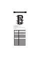
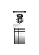
FUNCTIONAL DESCRIPTION & SPECIFICATIONS OF HI 8633 1) 2) 3) 4) 5) 6) Liquid Crystal Display Measurement range selection keys EC calibration knob Manual temperature compensation knob Temperature selection key On/Off key Range 0.0 to 199.9 / 0 to 1999 µS/cm 0.00 to 19.99 / 0.0 to 199.9 mS/cm Resolut ion 0.1 / 1 µS/cm 0.01 / 0.
FUNCTIONAL DESCRIPTION & SPECIFICATIONS OF HI 8733 1) 2) 3) 4) 5) Liquid Crystal Display Measurement range selection keys EC calibration knob Automatic Temperature Compensation coefficient knob On/Off key Range 0.0 to 199.9 / 0 to 1999 µS/cm 0.00 to 19.99 / 0.0 to 199.9 mS/cm Resolut ion 0.1 / 1 µS/cm 0.01 / 0.
FUNCTIONAL DESCRIPTION & SPECIFICATIONS OF HI 8734 1) 2) 3) 4) 5) 6) Liquid Crystal Display Measurement range selection keys TDS calibration knob Manual temperature compensation knob Temperature selection key On/Off key Range 0.0 to 199.9 / 0 to 1999 mg/L 0.00 to 19.99 g/L Resolut ion 0.1 / 1 mg/L 0.
OPERATIONAL GUIDE • Each meter is supplied complete with a 9V battery. Remove the battery compartment cover on the back of the meter (see page 16). Install the battery while observing its polarity. • Connect the probe to the meter securely by aligning the pins with the socket and pushing the plug in. • Make sure that the meter has been calibrated before taking any measurements (see “Calibration” section). • Immerse the conductivity probe into the sample, with the holes on the shaft completely submerged.
Note: If the display shows only a “1” on the far left hand side, the meter is out of range. Select the next (higher) range. • Wait for a couple of minutes for the temperature sensor to reach thermal equilibrium with the sample before taking measurements. • After the measurement has been completed, the instrument should be switched off and the probe should be cleaned and dried (see “Probe Maintenance” on page 17).
CALIBRATION Accessories needed: • Use any calibration solution within the meter’s range. The solution should ideally be close to the samples being measured. Use for example HI 7030 or HI 8030, 12880 µS/cm (=12.88 mS/cm) conductivity solution, for HI 8633 and HI 8733, and HI 7032, 1382 mg/L (=2764 µS/cm) TDS solution, for HI 8734. • ChecktempC or another accurate thermometer with 0.1°C resolution (not necessary for HI 8733).
• Press and hold down Temp to display the temperature. • Adjust the TEMPERATURE knob to display 20°C. • Release Temp key to display conductivity measurement. • Select 19.99 mS/cm (HI 8633) or 1999 mg/L (HI 8734) range by pressing the appropriate range key. • Follow LCD calibration indication. Adjust the calibration knob until the display shows for HI 8633 the conductivity reading at 25°C (see the conductivity vs. temperature table), e.g. @ 25°C, 12880 µS/cm = 12.
The instrument should be recalibrated at least once a month, or when the probe is changed. Note: For more accurate results, it is advisable to use a calibration solution close to the measurement range. See the “Accessories” section for a wide selection of conductivity solutions. PROCEDURE FOR HI 8733 • Pour sufficient quantity of a conductivity calibration solution (e.g. HI 7030/ HI 8030) into a beaker to cover the holes on the probe. If possible, use plastic beakers to minimize any EMC interference.
• Follow LCD calibration indication. Adjust the calibration knob until the display shows “12.88 mS” i.e. the conductivity reading @ 25°C. • All subsequent measurements will be compensated to 25°C (77°F). If you prefer to standardize the temperature compensation to 20°C (68°F) rather than 25°C (77°F), adjust the knob to read “11.67 mS” (see the conductivity vs. temperature chart on page 13). All subsequent measurements will be compensated to 20°C.
CONDUCTIVITY VERSUS TEMPERATURE CHART The conductivity of an aqueous solution is the measure of its ability to carry an electrical current by means of ionic motion. The conductivity invariably increases with increasing temperature. It is affected by the type and number of ions in the solution and by the viscosity of the solution itself. Both parameters are temperature dependent.
TDS TEMPERATURE VERSUS CHART The TDS value in aqueous solutions is directly proportional to conductivity. The ratio between the two parameters depends on the solution and usually it is set to a factor of 0.5 (corresponding to a solution of CaCO3). This means that 1 µS/cm is equal to 0.5 mg/L (ppm) of TDS. For manual temperature compensation, refer to the following chart: HI7032 HI7036 mg/L g/L (ppm) (ppt) ºC ºF 0 32 758 6.82 5 41 876 7.88 10 50 999 8.99 15 59 1122 10.10 16 60.
DETERMINING THE TEMPERATURE COEFFICIENT OF A SOLUTION (HI 8733) Highly acidic, alkaline samples or solutions with high salt content might have a different coefficient than the customary 2% per degree °C. In order to calculate this coefficient follow the procedure below: • Immerse the probe of HI 8733 in the sample and adjust the TEMPERATURE COEFFICIENT knob to 0% (i.e. no compensation). • Condition the sample and probe to 25°C and note the conductivity reading, C25.
BATTERY REPLACEMENT When battery becomes weak the meter will display the battery symbol as empty. When the low battery indicator appears, the battery has only a few hours left. A low battery will result in unreliable measurements. It is recommended to replace the battery immediately. Battery replacement must only take place in a nonhazardous area using a 9V alkaline battery. Unscrew the three screws on the rear of the meter, remove the battery compartment cover and replace the 9V battery with a new one.
PROBE MAINTENANCE Rinse the probe with tap water after every series of measurements. If a more thorough cleaning is required, remove the PVC sleeve and clean the probe with a cloth or a nonabrasive detergent. When reinserting the sleeve onto the probe, be sure that the sleeve is in the right direction with the four holes towards the cable end. After cleaning the probe, recalibrate the instrument. The probe body is in PVC. For this reason it must never come into close contact with a heat source.
ACCESSORIES CALIBRATION SOLUTIONS HI 7030L HI 7030M HI 7031L HI 7031M HI 7033L HI 7033M HI 7034L HI 7034M HI 7035L HI 7035M HI 7039L HI 7039M HI 7032L HI 7032M HI 7036L HI 7036M 12880 µS/cm, 500 mL bottle 12880 µS/cm, 230 mL bottle 1413 µS/cm, 500 mL bottle 1413 µS/cm, 230 mL bottle 84 µS/cm, 500 mL bottle 84 µS/cm, 230 mL bottle 80000 µS/cm, 500 mL bottle 80000 µS/cm, 230 mL bottle 111800 µS/cm, 500 mL bottle 111800 µS/cm, 230 mL bottle 5000 µS/cm, 500 mL bottle 5000 µS/cm, 230 mL bottle 1382 ppm (mg/L),
RECOMMENDATIONS FOR USERS Before using these products, make sure they are entirely suitable for the environment in which they are used. Operation of these instruments in residential areas could cause unacceptable interferences to radio and TV equipment, requiring the operator to follow all necessary steps to correct interferences. The metal band at the end of the probe is sensitive to electrostatic discharges. Avoid touching this metal band at all times.
Hanna Instruments Inc. Highland Industrial Park 584 Park East Drive Woonsocket, RI 02895 USA Technical Support for Customers Tel. (800) 426 6287 Fax (401) 765 7575 E-mail tech@hannainst.com www.hannainst.