
User Guide

5
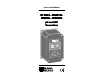
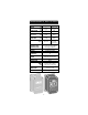
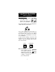
TERMINAL BOARD CONNECTIONS
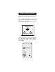
Remove the 4 screws and take the top cover
off.
There are three cable glands on the cover of
the transmitter: two smaller ones and a large
one. The large cable gland with the split in the
rubber is for the electrode.
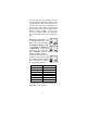
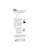
ELECTRODE
CABLE GLAND
WIRE CABLE GLANDS
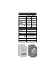
Connect the positive supply to the strip termi-
nal "+VE LOOP" and the negative supply to
the terminal "-VE LOOP" of the transmitter
terminal block.
SLOPE ADJUSTMENT
OFFSET ADJUSTMENT
INPUT
-VE LO
O
P
+VE LO
O
P
TEM
P
. PR
O
BE