Instruction Manual HI 8614 - HI 8614L HI 8615 - H HII 8615L pH and ORP Transmitter s ransmitters pH L HI 861A4TOR pH INDIC ITTER SM & TRAN These Instruments are in Compliance with the CE Directives http://www.hannainst.
Dear Customer, Thank you for choosing a Hanna Instruments Product. Please read this instruction manual carefully before using the instrument. This manual will provide you with all the necessary information for the correct use of the instrument, as well as a precise idea of its versatility in a wide range of applications. These instruments are in compliance with the directives EN 50081-1 and EN 50082-1. TABLE OF CONTENTS Preliminary Examination ............................ 1 General Description ............
PRELIMINARY EXAMINATION Remove the instrument from the packing material and examine it carefully to make sure that no damage has occurred during shipping. If there is any noticeable damage, notify your Dealer. Note: Save all packing material until you are sure that the instrument functions correctly. All defective items must be returned in the original packing material together with the supplied accessories.
The transmitters use a universal BNC socket for quick and secure connection to any electrode with a BNC connector. For HI 8614 - HI 8614L: temperature compensation is performed by the transmitter's ATC circuitry when measurements are taken with the temperature probe attached (HI 76608, optional); it is also possible to substitute the temperature probe with a fixed resistor if ATC is not required.
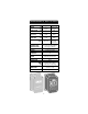
SPECIFICATIONS OF HI 8614 & HI 8614L HI8614 HI8614L RANGE pH mA ---4 to 20 0.00 to 14.00 4 to 20 RESOLUTION pH mA ---0.01 0.01 0.01 ACCURACY @20°C/68°F pH mA ---±0.02 ±0.02 ±0.02 TYPICAL EMC DEVIATION pH mA ---±0.25 ±0.2 ±0.25 CALIBRATION Offset: Slope: TEMPERATURE COMPENSATION ±2.2 mA ±0.5 mA ±2.2 mA/±2 pH ±0.5 mA 86 to 116% Fixed/automatic 0 to 100°C (32 to 212°F) with HI76608 temp.
SPECIFICATIONS OF HI8615 & HI8615L HI8615 HI8615L RANGE mV mA ---4 to 20 0 to ±1000 4 to 20 RESOLUTION mV mA ---0.01 1 0.01 ACCURACY @20°C/68°F mV mA ---±0.02 ±5 ±0.02 TYPICAL EMC DEVIATION mV mA ---±0.25 ±15 ±0.25 CALIBRATION Offset: Slope: ±0.8 mA ±0.8 mA ±0.8 mA/±100mV ±0.8 mA 90 to 110% 1012 ohm INPUT IMPEDANCE OUTPUT 4 to 20 mA isolated INSTALLATION CATEGORY II without LCD: 18 to 30VDC with LCD 20 to 36VDC POWER LOAD Max. 500 ohms PROTECTION ENVIRONMENT TEMP.
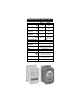
TERMINAL BOARD CONNECTIONS Remove the 4 screws and take the top cover off. There are three cable glands on the cover of the transmitter: two smaller ones and a large one. The large cable gland with the split in the rubber is for the electrode. ELECTRODE CABLE GLAND WIRE CABLE GLANDS Connect the positive supply to the strip terminal "+VE LOOP" and the negative supply to the terminal "-VE LOOP" of the transmitter terminal block. SLOPE ADJUSTMENT TEMP.
TEMP. PROBE -VE LOOP -VE LOOP +VE LOOP TEMP. PROBE TEMP. PROBE INPUT -VE LOOP For HI 8614 & HI 8614L only: for automatic temperature compensation, connect the 2 terminals of the temperature probe (HI 76608, optional) to "TEMP. PROBE" terminals. If automatic temperature compensation is not required, short the "TEMP. PROBE" terminals with a resistance according to the external temperature: INPUT +VE LOOP Electrode connection: connect the BNC of the cable to the BNC socket on the transmitter.
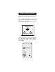
TEMP. PROBE -VE LOOP Initial preparation: • Connect the pH electrode to the BNC socket. • Connect the temperature probe to the transmitter. +VE LOOP pH CALIBRATION WITH AUTOMATIC TEMPERATURE COMPENSATION (HI 8614 & HI 8614L) INPUT 04 70 HI Pour small quantities of pH 7.01 and pH 4.01 solution into two clean beakers. HI 7004 HI 7007 For accurate calibration use two beakers for each buffer solution, the first one for rinsing the electrode, the second one for calibration.
Procedure: • Disconnect the +ve supply cable from "+VE LOOP" terminal and connect a 20mA f.s. ammeter between the +ve cable and "+VE LOOP" terminal. • Remove the protective cap from the electrode, rinse it with some pH 7.01 solution or immerse it in the pH 7 rinse solution, then immerse the pH electrode and temperature probe into pH 7.01 calibration buffer solution; shake briefly and wait for the reading to stabilize.
For other buffer temperatures, refer to page 11 for the appropriate mA / pH reading. • • Rinse the electrode with tap water or distilled water and a small amount of pH 4.01 or 10.01 buffer solution or immerse it in the pH 4 rinse solution (2nd calibration point). Dip the HI 7004 electrode and the temperature probe into pH 4.01 (or 10.01) calibration buffer solution, shake briefly and wait for a few minutes for reading to stabilize. Adjust the slope trimmer until the ammeter reads 8.
Under normal application, adjustment on this module may not be necessary. If routine check is required, the following procedures shall be performed. • Follow the procedure at page 7 to perform calibration on the transmitter module (using a ammeter). • Simulate a 4.00 mA loop current for the transmitter (i.e. pH 0.00 as Electrode input) and check for display reading. • Simulate a 20.00 mA loop current for the transmitter (i.e. pH 14.00 as Electrode input) and check for display reading.
pH CALIBRATION WITH FIXED TEMPERATURE COMPENSATION (HI 8614 & HI 8614L only) Connect the appropriate resistor to the "TEMP. PROBE" terminals (see page 6) depending on the temperature of the calibration solution. • TEMP. PROBE • °C -VE LOOP Take the temperature of the buffer solutions using a Checktemp or a thermometer with a resolution of at least 1°.
ORP CALIBRATION (HI8615 & HI8615L) 20 70 HI Initial preparation: Disconnect the +ve supply cable from the "+VE LOOP" terminal and connect a 20 mA f.s. ammeter between the +ve cable and the "+VE LOOP" terminal. With HI 8615L the instrument display can be used during calibration without the need to connect the ammeter. In this case the values are directly expressed in mV units. -VE LOOP +VE LOOP Pour a small quantity of HI 7020 ORP solution into a beaker.
• If the reading lies outside this range, adjust the slope adjustment trimmer on the transmitter for a reading just within this range. The unit is now calibrated. SLOPE ADJUSTMENT OFFSET ADJUSTMENT A complete calibration of the transmitter module is advised periodically. This calibration procedure requires the HI 8427 or the HI 931001 pH and ORP simulator to simulate the ORP electrode. HI 8427 or HI 931001 produce a known signal into the system so that the faults of the system can be isolated.
• Set the simulator to 350 mV and adjust the slope trimmer to read 14.8 mA on the ammeter or 350 mV on the HI 8615L display (HI 8615L only). mA SLOPE ADJUSTMENT OFFSET ADJUSTMENT -VE LOOP Connect the ORP electrode to the module and immerse the tip of the electrode into the beaker of HI 7020 ORP solution and check that the ammeter reading lies between 13.6 and 14.2 mA or the instrument reading is between 200 and 275 mV at 25°C (HI 8615L only).
FOR HI 8615L ONLY: The HI 8615L is factory calibrated, and the displayed values are referenced to the 4-20 mA loop current (e.g. LCD displays -1000 mV when loop current is 4.00 mA and displays +1000 mV when current is 20.00 mA). Under normal application, adjustment on this module may not be necessary. If routine check is required, the following procedures shall be performed. • Simulate a 12.00 mA loop current for the transmitter (i.e. 0 mV at Electrode input) and check display reading.
Please note: -1000 0 1000 350 200 275 1 mV mV mV mV mV mV mV = = = = = = = 4 12 20 14.8 13.6 14.2 12.008 mA mA mA mA mA mA mA Note: when the meter is used in conjunction with the Hanna indicator HI 8512T, or the controller HI 8720T, the calibration can also be performed on the indicator/controller. In this case slight adjustment can be made on the indicator/controller even if the whole system calibration is advised, always starting from the transmitter.
ELECTRODE CONDITIONING AND MAINTENANCE Reference Filling Hole Reference Filling Hole Sensitive Wire Reference Wire Reference Wire Sensitive Wire Reference Junction Reference Junction Glass Bulb Glass Bulb Plastic Body pH Electrode Reference Wire Reference Junction Platinum or Gold tip Glass Body pH Electrode Reference Wire Reference Junction Platinum or Gold tip Plastic Body ORP Electrode Glass Body ORP Electrode PREPARATION Remove the protective cap.
do with a glass thermometer. If the bulb and/or junction are dry, soak the electrode in HI70300 or HI 80300 Storage Solution for at least one hour. For refillable electrodes: If the fill solution (electrolyte) is more than 1 cm (½") below the fill hole, add HI 7082 or HI 8082 3,5M KCl Electrolyte Solution for double junction or HI 7071 or HI 8071 3,5M KCl+AgCl Electrolyte Solution for single junction electrodes. For a faster response unscrew the fill hole screw during measurements.
PERIODIC MAINTENANCE Inspect the electrode and the cable. The cable used for connection to the meter must be intact and there must be no points of broken insulation on the cable or cracks on the electrode stem or bulb. Connectors must be perfectly clean and dry. If any scratches or cracks are present on the electrode body, replace the electrode. Rinse off any salt deposits with water.
TROUBLESHOOTING Evaluate your electrode performance based on the following. • Noise (Readings fluctuate up and down) could be due to: - Clogged/Dirty Junction: Refer to the Cleaning Procedure above. - Loss of shielding due to low electrolyte level (in refillable electrodes only): HI 7071 or HI 8071 for single junction or HI 7082 or HI 8082 for double junction electrodes. • Dry Membrane/Junction: Soak in Storage Solution HI 70300 or HI 80300 for at least 1 hour.
TEMPERATURE-RESISTANCE CORRELATION FOR HANNA pH SENSITIVE GLASS The resistance of glass electrodes partially depends on the temperature. The lower the temperature, the higher the resistance. It takes longer time for the reading to stabilize if the resistance is higher. In addition, the response time will suffer to a greater degree at temperatures below 10°C.
Typical Electrode Life Ambient Temperature 1- 3 years 90 °C Less than 4 months 120°C Less than 1 month High concentrations of sodium ions interfere with readings in alkaline solutions; the pH at which the interference starts to be significant depends upon the composition of the glass. This interference is the alkaline error and causes the pH to be underestimated. Hanna's glass formulations have the indicated characteristics.
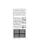
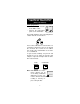
INSTALLATION PROCEDURE AND EXAMPLES The HI 8614, HI 8614L, HI 8615 and HI 8615L transmitters may be wall mounted in any convenient location near the measurement point. To minimize thermal drift due to extreme temperature fluctuations during the measurement process, particularly if the measurement is conducted outdoors, it is best to protect the transmitter in an enclosed casing.
Monitoring the pH/ORP with Panel Mounting pH (HI 8510)/ORP (HI 8512) Indicator Controlling the pH/ORP with an Industrial Regulator Monitoring and Controlling the pH/ORP with Panel Mounting Indicator/Regulator and Dosage Control of either Acid or Base 24
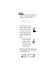
Monitoring and Controlling the pH with (HI 8711) Panel Mounting Indicator/ Regulator with Independent Dosage Control for Acid and Base 25
ACCESSORIES pH CALIBRATION SOLUTIONS HI 7004M pH 4.01 Buffer Solution, 230 mL HI 7004L pH 4.01 Buffer Solution, 460 mL HI 7006M pH 6.86 Buffer Solution, 230 mL HI 7006L pH 6.86 Buffer Solution, 460 mL HI 7007M pH 7.01 Buffer Solution, 230 mL HI 7007L pH 7.01 Buffer Solution, 460 mL HI 7009M pH 9.18 Buffer Solution, 230 mL HI 7009L pH 9.18 Buffer Solution, 460 mL HI 7010M pH 10.01 Buffer Solution, 230 mL HI 7010L pH 10.
pH ELECTRODES HI 1090T Screwcap PG13.5 connector, double junction, glass-body PG13.5 THREAD φ 12mm 30mm φ 9.5mm 110mm HI 1110S Screw connector, single junction, glass-body HI 1130B/3 BNC connector, 3 m (9.9') cable, single junction, glass-body M13 x 1.5 DIA 16 mm DIA 9.5mm DIA 12mm 3/4 x 16 UNF DIA 20.5mm 25 7 mm mm 38.5mm 110mm HI 1110S HI 1130B/3 HI 1110T Screwcap PG13.5 connector, double junction, glass-body PG13.5 THREAD φ 12mm 30mm φ 9.
HI 1210T Screwcap PG13.5 connector, double junction, plastic-body PG13.5 THREAD φ 12mm 30mm HI 1910B 110mm BNC connector, 1 m (3.3') cable, double junction, plastic-body, built-in amplifier 3/4 x 16 UNF DIA 12mm DIA 20.5mm 38.5mm HI 1911B 110mm BNC connector, 1 m (3.3') cable, double junction, plastic-body, built-in amplifier 3/4 x 16 UNF DIA 12mm DIA 20.5mm 38.5mm 110mm HI 1912B BNC connector, 1 m (3.
HI 2910B/5 BNC connector, 5 m (16.5') cable, double junction, plastic-body, built-in amplifier 3/4 x 16 UNF DIA 12mm DIA 20.5mm 38.5mm 110mm ORP ELECTRODES HI 2930B/5 BNC connector, 5 m (16.5') cable, Pt, Ultem®-body, built-in amplifier 3/4 x 16 UNF DIA 12mm DIA 20.5mm 38.5mm 110mm HI 3110S Screw-type connector, Pt, glassbody HI 3130B/3 BNC connector, 3 m (9.9') cable, Pt, glass-body M13 x 1.5 DIA 16 mm 3/4 x 16 UNF DIA 12mm DIA 20.5mm 25 7 mm mm 38.
HI 3210T Screwcap PG13.5 connector, Pt, plastic-body PG13.5 THREAD φ 12mm 30mm 110mm HI 3410S Screw connector, Pt, plastic-body HI 3430B/3 BNC connector, 3 m (9.9') cable, Pt, plastic-body 3/4 x 16 UNF M13 x 1.5 DIA 16 mm DIA 12mm DIA 20.5mm 25 7 mm mm 38.5mm HI 3410S 110mm HI 3430B/3 HI 3932B/5 BNC connector, 5 m (16.5') cable, Pt, Ultem®-body, built-in amplifier 3/4 x 16 UNF DIA 12mm DIA 20.5mm 38.5mm 110mm HI 4110S Screw-type connector, Au, glassbody HI 4130B/3 BNC connector, 3 m (9.
EXTENSION CABLES FOR SCREW-TYPE ELECTRODES ONLY (SCREW TO BNC CONNECTOR) HI 7855 SERIES CABLE CONNECTORS CONNECTOR AND 3.0 mm (0.12") CABLE WITH BNC CONNECT TO THE BNC SOCKET OF THE METER CONNECT TO SCREW TYPE ELECTRODES HI7855/1 HI7855/3 HI7855/5 HI7855/10 HI7855/15 Extension cable 1m (3.3') long Extension cable 3m (9.9') long Extension cable 5m (16.5') long Extension cable 10m (33') long Extension cable 15m (49.5') long OTHER ACCESSORIES BL PUMPS Dosing Pumps with Flow Rate from 1.
WARRANTY All Hanna Instruments meters are warranted for two years against defects in workmanship and materials when used for their intended purpose and maintained according to instructions. The probes and the electrodes are warranted for a period of six months. Damages due to accident, misuse, tampering or lack of prescribed maintenance are not covered. This warranty is limited to repair or replacement free of charge. If service is required, contact the dealer from whom you purchased the instrument.
h t t p : / / w w w . h a n n a i n s t .
CE DECLARATION OF CONFORMITY DECLARATION OF CONFORMITY We Hanna Instruments Srl V.le delle industrie 12 35010 Ronchi di Villafranca (PD) ITALY herewith certify that the pH and ORP transmitters HI 8614 HI 8614L HI8615 HI8615L have been tested and found to be in compliance with the following regulations: IEC 801-2 IEC 801-3 IEC 801-4 EN 55022 Electrostatic Discharge RF Radiated Fast Transient Radiated, Class B Date of Issue: 01-04-1996 D.Volpato - Engineering Manager On behalf of Hanna Instruments S.