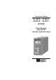
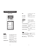
Instruction Manual HI 8510 • HI 8512 HI 8710 • HI 8711 HI 8720 Panel Mounted pH and ORP Indicators and Controllers ORP HI 8720E mV DOSAGE OXID. REDUC. MEA SURE SET SLOPE ΔAL COARSE ΔAL SET FINE 0 mV TEST 500 mV TEST www.hannainst.
PRELIMINARY EXAMINATION Dear Customer, Thank you for choosing a HANNA instruments® product. Please read this instruction manual carefully before using the instrument. If you need additional technical information, do not hesitate to e-mail us at tech@hannainst.com. These instruments are in compliance with the directives. Remove the instrument from the packing material and examine it carefully to make sure that no damage has occurred during shipping.
AVAILABLE MODELS HI 8510E020 HI 8510E420 HI 8510T020 HI 8510T420 HI 8512E020 HI 8512E420 HI 8512T020 HI 8512T420 HI 8710E020 HI 8710E420 pH indicator with electrode input and 0-20 mA recorder output pH indicator with electrode input and 4-20 mA recorder output pH indicator with input from transmitter and 0-20 mA recorder output pH indicator with input from transmitter and 4-20 mA recorder output HI 8710T020 ORP indicator with electrode input and 0-20 mA recorder output ORP indicator with electr
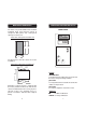
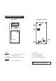
MECHANICAL DIMENSIONS FUNCTIONAL DESCRIPTION HI 8510 The meters are provided with a black anodized aluminum body, front and back panels in shockproof ABS plastic and a transparent splash-proof front cover. FRONT PANEL pH Front view of the panel-mounted unit HI 8510E pH 141mm 5.55" 144mm 5.67" SLOPE Δ 69mm 2.71" 72mm 2.83" SENSOR TEST The dimensions show the cutout size for the installation. pH 7 TEST pH 4 TEST Side view of the panel-mounted unit 0.25/4mm 0.01/0.
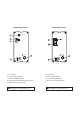
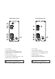
REAR PANEL HI 8510T REAR PANEL HI 8510E ELECTRODE INPUT 5 4 3 PT100 + mA OUT - FUSE 1 FUSE 220 110 L 2 1. Fuse holder 2. Power supply terminals 3. Recorder output terminals 4. Connections for Pt100 temperature sensor 5. BNC socket for pH electrode Unplug the instrument from the power supply before replacing the fuse. 8 1. Fuse holder 2. Power supply terminals 3. Recorder output terminals 4. Connections to the transmitter Unplug the instrument from the power supply before replacing the fuse.
FUNCTIONAL DESCRIPTION HI 8512 REAR PANEL HI 8512E FRONT PANEL ORP HI 8512E ELECTRODE INPUT 4 mV 3 + mA OUT - SLOPE FUSE 0 mV TEST 500 mV TEST 1 FUSE 220 110 L 2 Keypad 0 mV TEST To verify the instrument calibration at 0 mV 500 mV TEST To verify the slope at 500 mV 1. Fuse holder 2. Power supply terminals 3. Recorder output terminals 4. BNC socket for ORP electrode Trimmers SLOPE For slope calibration Unplug the instrument from the power supply before replacing the fuse.
FUNCTIONAL DESCRIPTION HI 8710 REAR PANEL HI 8512T FRONT PANEL pH HI 8710E pH SLOPE ACID BASE Δ0 MEA SURE ΔAL SET COARSE SENSOR TEST ΔAL pH 7 TEST pH 4 TEST SET FINE Keypad SET MEASURE To set the pH dosage limit To enter measurement mode and to enable diagnostic tests SENSOR TEST To display electrode mV reading and verify its working condition ΔAL To display & set alarm tolerance pH 7 TEST To verify Offset compensation pH 4 TEST To verify amplifier circuit Trimmers ΔO SLOPE ΔAL SET/COARSE SET
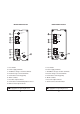
REAR PANEL HI 8710T REAR PANEL HI 8710E ELECTRODE INPUT 9 8 7 3 5 PT100 + mA OUT OPEN: ACID SHORT: BASE SET 4 CONSENT 6 ALARM FUSE 1 FUSE 220 110 L 2 1. Fuse holder 2. Power supply terminals 3. Acid/Basic dosage selection terminals 4. Red/ox dosage consent terminals 5. Connections for dosing pump 6. Alarm contacts 7. Recorder output contacts 8. Connections for Pt100 temperature sensor 9. BNC socket for pH electrode Unplug the instrument from the power supply before replacing the fuse.
FUNCTIONAL DESCRIPTION HI 8711 ΔAl FRONT PANEL pH 7 TEST pH HI 8711E pH 4 TEST pH Trimmers ΔO SLOPE ΔAL For Offset calibration For Slope calibration To set the tolerance of the alarm ACID SET/COARSE To coarsely adjust acid setpoint ACID SET/FINE To finely adjust acid setpoint BASE SET/COARSE To coarsely adjust basic setpoint BASE SET/FINE To finely adjust basic setpoint SLOPE ACID SET BASE SET Δ ΔAL MEA SURE COARSE ACID SET SENSOR TEST ΔAL FINE COARSE pH 7 TEST pH 4 TEST Keypad ACID SET BAS
REAR PANEL HI 8711E ELECTRODE INPUT 8 7 REAR PANEL HI 8711T PT100 6 + mA OUT - 4 BASE 3 ACID 5 ALARM FUSE 1 FUSE 220 110 L 2 1. Fuse holder 2. Power supply terminals 3. Connections for dosing pump for acid 4. Connections for dosing pump for base 5. Alarm contacts 6. Recorder output contacts 7. Connections for Pt100 temperature sensor 8. BNC socket for pH electrode Unplug the instrument from the power supply before replacing the fuse. 18 18£ 1. Fuse holder 2. Power supply terminals 3.
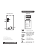
FUNCTIONAL DESCRIPTION HI 8720 FRONT PANEL ORP Trimmers SLOPE ΔAL For Slope calibration To display and set the alarm tolerance SET/COARSE To coarsely adjust the setpoint SET/FINE To finely adjust the setpoint HI 8720E mV DOSAGE OXID. REDUC.
REAR PANEL HI 8720E ELECTRODE INPUT 8 4 7 3 5 CONSENT + mA OUT OPEN: OXD SHORT: RDX SET FUSE 6 REAR PANEL HI 8720T ALARM 1 FUSE 220 110 L 2 1. Fuse holder 2. Power supply terminals 3. Ox/Red dosage selection terminals 4. Ox/red dosage consent terminals 5. Connections for dosing pump 6. Alarm contacts 7. Recorder output contacts 8. BNC socket for ORP electrode 1. Fuse holder 2. Power supply terminals 3. Ox/Red dosage selection terminals 4. Ox/red dosage consent terminals 5.
HI 8710E SPECIFICATIONS Range Resolution 0.01 pH Accuracy HI 8510E Range Accuracy ±0.02 pH Typical EMC Dev. Calibration ±0.5% ±0.1 pH / ±0.2 mA Installation Category 10 Ohm 4 to 20 mA Offset: ±2 pH with Δ0 trimmer Slope: 80 to 110% with slope trimmer Temperature Compensation Fixed or automatic with Pt100 from 0 to 100°C (32 to 212°F) Recorder Output Power Supply 115 or 230 Vac; 50/60 Hz -10 to 50°C (14 to 122°F); RH max 95% non condensing Panel Cutout 141 x 69 mm (5.6 x 2.
HI 8720E Range ±1000 mV Resolution 1 mV Accuracy ±5 mV Typical EMC Dev. Relays 10 Ohm 4 to 20 mA Slope: 90 to 110% with slope trimmer • 1 for setpoint and 1 for alarm, max 2A, 240 V resistive load (isolated) Recorder Output Power Supply II 12 Input ±0.5% ±6 mV / ±0.2 mA Installation Category Calibration • HI 8720T • 0-20 mA or 4-20 mA (isolated) 115 or 230 Vac; 50/60 Hz Environment -10 to 50°C (14 to 122°F); RH max 95% non condensing Panel Cutout 141 x 69 mm (5.6 x 2.
• The HI 8710 models are single dosage controllers with acid/alkaline selection. If acid dosage is needed (e.g. in chromium VI reduction), leave open the ACID/BASE selection terminals (see picture), while for alkaline dosage (e.g. in cyanide oxidation), make a short circuit across the ACID/BASE selection terminals with a jumper wire. The HI 8720 models are single dosage controllers with oxidant/reductant selection. If oxidant dosage is needed (e.g.
Using a small screwdriver adjust the ACID SET COARSE and FINE trimmers to display the desired acid set value. OPERATIONAL GUIDE All instrument settings are made via front panel keys and trimmers. When each key is pressed, the corresponding LED lights up to show the operating function. If using a model with input from electrode, make sure that the meter is calibrated before starting any operation (see "Calibration" section for details).
When acid dosage is active, the ACID LED lights up, while during alkaline dosage, the BASE LED turns on (HI 8710 only). ΔAL ΔAL pH Examples: For HI 8710, if the set value is pH 3 and the ΔAlarm is 1.5 pH, the instrument generates an alarm every time the pH reading is higher than 4.5 pH or lower than 1.5pH. For HI 8711, if the set values are pH 7 and pH 8, and the Δ Alarm is 1.5 pH, the instrument generates an alarm every time the pH reading is higher than 9.5 pH or lower than 5.5 pH.
Rinse pH electrode and thermometer probe thoroughly with water, then immerse them in pH4.01 (HI 7004) or pH 10.01 (HI 7010) buffer solution. Note: For accurate readings, use pH 4.01 if you are going to measure acid samples or pH 10.01 for alkaline measurements. pH CALIBRATION Make sure that the instrument is in measurement mode (MEASURE LED is on) before proceeding with calibration. Measure the temperature of the calibration buffer with a ChecktempC or another accurate thermometer.
pH VALUES AT VARIOUS TEMPERATURE pH DIAGNOSTIC TESTS Temperature has an effect on the pH. The calibration buffer solutions are affected by temperature changes to a lesser degree than normal solutions. HI 8510, HI 8710 and HI 8711 are provided with autodiagnostic functions that allow to check and troubleshoot any malfunctioning. The functions are made via front panel keys to isolate the cause of malfunction whether it is due to pH electrode contamination, internal offset circuit or amplifier circuit.
B) Internal Offset Circuit Test Press the pH7 TEST key and the display should show a value within 7±1 pH, to verify the internal circuit of the meter in terms of the offset compensation. pH 7 TEST pH C) Amplifier Circuit Test Press the pH4 TEST key and the display should show a value within the 3.30 to 4.30 pH range, to verify the amplifier circuit of the meter.
LED INDICATION TAKING REDOX MEASUREMENTS All LEDs above the keys indicate the state of each function, whether it is active or the display is indicating the mode. Redox measurements allow the quantification of the solution oxidizing/reducing power, and are commonly expressed in mV. Oxidation may be defined as the process during which a molecule (or an ion) loses electrons and reduction as the process by which electrons are gained.
Generally, if the ORP (mV) reading corresponding to the pH solution value is higher than the value in the table below, an oxidizing pre-treatment is necessary; otherwise a reducing pre-treatment is necessary: pH 0 5 10 mV pH mV pH 990 1 920 2 680 6 640 7 400 11 340 12 mV pH mV pH 860 3 800 4 580 8 520 9 280 13 220 14 mV 740 460 160 Reducing pre-treatment: immerse the electrode for some minutes in HI 7091 solution. Oxidizing pre-treatment: immerse the electrode for some minutes in HI 7092 solution.
If the bulb and/or junction are dry, soak the electrode in HI 70300 storage solution for at least one hour. For refillable electrodes: If the internal electrolyte solution is more than 1 cm (½") below the filling hole, add HI 7082 solution (3.5M KCl) for double junction electrodes or HI 7071 (3.5M KCl+AgCl) for single junction electrodes. For a faster response unscrew the filling hole screw during measurements.
TROUBLESHOOTING Evaluate your electrode performance based on the following: • Noise (readings fluctuate up and down) could be due to: - Clogged/Dirty Junction: refer to the above "Cleaning Procedure" - Loss of shielding due to low electrolyte level (in refillable electrodes only): refill with HI 7071 solution for single junction or HI 7082 for double junction electrodes • Dry Membrane/Junction: soak in HI70300 storage solution for at least 1 hour • Drifting: soak the electrode tip in warm HI7082 solution fo
of regular cable up to 50 m (165'), can be installed without special connectors. AmpHel® electrodes feature a built-in a microamplifier to boost the signal, drastically reducing susceptibility to noise and drift. The sealed electrode body can stand a moisture up to 100% RH without any effect on the signal.
DIA 16.5mm 5mm DIA 7.6mm pH ELECTRODES M13 x 1.5 HI 1090T Screwcap PG13.5 connector, double junction, glass body PG13.5 THREAD φ 12mm φ 9.5mm 25 7 mm mm 25mm HI 1115S HI 1210T 30mm DIA 12mm DIA 16 mm 110mm 150mm HI 1135B/3 Screwcap PG13.5 connector, double junction, plastic body PG13.5 THREAD Screw connector, single junction, glass body HI 1130B/3 BNC connector, 3 m (9.9') cable, single junction, glass body φ 12mm HI 1110S M13 x 1.5 DIA 16 mm 3/4 x 16 UNF 30mm HI 1910B DIA 9.
HI 2114B/5 BNC connector, 5 m (16.5') cable, double junction, plastic body 3/4 x 16 UNF HI 3210T Screwcap PG13.5 connector, Pt, plastic body PG13.5 THREAD DIA 12mm φ 12mm DIA 20.5mm 38.5mm 110mm HI 2910B/5 BNC connector, 5 m (16.5') cable, double junction, plastic body, builtin amplifier 3/4 x 16 UNF DIA 12mm DIA 20.5mm DIA 16 mm 110mm ORP ELECTRODES HI 2930B/5 BNC connector, 5 m (16.
OTHER ACCESSORIES HI 98501 ChecktempC thermometer with penetration probe and 0.1°C resolution (-50.0 to 150.0°C) HI 8614 pH transmitter HI 8614L pH transmitter with display HI 8615 ORP transmitter HI 8615L ORP transmitter with display BL PUMPS Dosing pumps with flow rate from 1.
SALES & TECHNICAL SERVICE Australia: Tel. (03) 9769.0666 • Fax (03) 9769.0699 China: Tel. (10) 88570068 • Fax (10) 88570060 Egypt: Tel. & Fax (02) 2758.683 Germany: Tel. (07851) 9129-0 • Fax (07851) 9129-99 Greece: Tel. (210) 823.5192 • Fax (210) 884.0210 Indonesia: Tel. (21) 4584.2941 • Fax (21) 4584.2942 Japan: Tel. (03) 3258.9565 • Fax (03) 3258.9567 Korea: Tel. (02) 2278.5147 • Fax (02) 2264.1729 Malaysia: Tel. (603) 5638.9940 • Fax (603) 5638.9829 Singapore: Tel. 6296.7118 • Fax 6291.