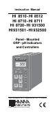
Instruction Manual HI 8510 - HI 8512 HI 8710 - HI 8711 HI 8720 - HI 931500 HI 931501 - HI 932500 Panel - Mounted ORP - pH Indicators and Controllers ORP HI 8720E mV DOSAGE OXID. REDUC. MEA SURE SET SLOPE ∆AL COARSE ∆AL SET FINE 0 mV TEST 500 mV TEST These Instruments are in Compliance with the CE Directives http://www.hannainst.
Dear Customer, Thank you for choosing a Hanna Instruments Product. Please read this instruction manual carefully before using the instrument. This manual will provide you with all the necessary information for the correct use of the instrument, as well as a precise idea of its versatility in a wide range of applications. These instruments are in compliance with directives. TABLE OF CONTENTS Preliminary Examination ............................. 3 General Description .....................................
PRELIMINARY EXAMINATION Remove the instrument from the packing material and examine it carefully to make sure that no damage has occurred during shipping. If there is any noticeable damage, notify your Dealer. Note: Save all packing materials until you are sure that the instrument functions correctly. All defective items must be returned in the original packing materials together with the supplied accessories.
Using the pH indicators in conjunction with a 4-20mA output pH transmitter HI 8614 or HI 8614L (with LCD display) and using the ORP indicators in conjunction with a 4-20 mA output ORP transmitter HI 8615 or HI 8615L (with LCD display) will assure you of a strong, interference-free signal at distances up to 300 m (1000 ft). All instruments are supplied with a plastic transparent front cover and mounting brackets (electrode and mains cable excluded).
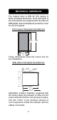
MECHANICAL DIMENSIONS The meters have a DIN 43 700 casing in black anodized aluminum. Front and back of the instruments are supplied with shockproof ABS plastic and a transparent protective cover for the front panel. Front view of the panel-mounted unit. 141mm 5.55" 144mm 5.67" 69mm 2.71" 72mm 2.83" These dimensions show the cutout size for the installation. Side view of the panel-mounted unit. 0.25/4mm 0.01/0.160" ADJUSTABLE LOCATION BRACKET 144mm 5.67" 135mm 5.31" 190mm MIN 7.
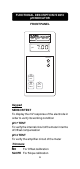
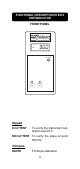
FUNCTIONAL DESCRIPTION HI 8510 pH INDICATOR FRONT PANEL pH HI 8510E pH SLOPE ∆ SENSOR TEST pH 7 TEST pH 4 TEST Keypad SENSOR TEST To display the mV response of the electrode in order to verify its working condition pH 7 TEST To verify the internal circuit of the meter in terms of Offset compensation pH 4 TEST To verify the amplifier circuit of the meter Trimmers ∆O For Offset calibration SLOPE For Slope calibration 6
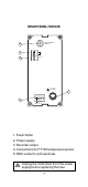
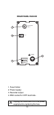
REAR PANEL HI 8510E ELECTRODE INPUT 5 4 3 PT100 + mA OUT - FUSE 1 FUSE 220 110 L 2 1. Fuse Holder 2. Power supply 3. Recorder output 4. Connections for PT100 temperature sensor 5. BNC socket for pH electrode. Unplug the instrument from the power supply before replacing the fuse.
REAR PANEL HI 8510T 1. Fuse Holder 2. Power supply 3. Recorder output 4. Connections to the transmitter. Unplug the instrument from the power supply before replacing the fuse.
FUNCTIONAL DESCRIPTION HI 8512 ORP INDICATOR FRONT PANEL ORP HI 8512E mV SLOPE 0 mV TEST 500 mV TEST Keypad 0 mV TEST To verify the instrument calibration at point 0 500 mV TEST To verify the slope at point 500 mV Trimmers SLOPE For Slope calibration 9
REAR PANEL HI 8512E ELECTRODE INPUT 4 3 + mA OUT - FUSE 1 FUSE 220 110 L 2 1. Fuse Holder 2. Power supply 3. Recorder output 4. BNC socket for ORP electrode. Unplug the instrument from the power supply before replacing the fuse.
REAR PANEL HI 8512T 1. Fuse Holder 2. Power supply 3. Recorder output 4. Connections to the transmitter. Unplug the instrument from the power supply before replacing the fuse.
FUNCTIONAL DESCRIPTION HI 8710 pH CONTROLLER WITH ALARM FRONT PANEL pH HI 8710E pH SLOPE ACID BASE ∆0 ∆AL MEA SURE SET SENSOR TEST ∆AL pH 7 TEST pH 4 TEST COARSE SET FINE Keypad SET To set the working point of pH dosage MEASURE To set HI 8710 on measurement mode and to enable the diagnostic tests SENSOR TEST To display the mV response of the electrode in order to verify its working condition To display and set the toler∆ AL ance of the alarm points pH 7 TEST To verify the internal circuit of t
Trimmers ∆O SLOPE ∆ AL For Offset calibration For Slope calibration To set the tolerance of the alarm SET/COARSE To coarsely adjust the set point SET/FINE To finely adjust the set point Leds ACID To show the acid dosage is active BASE To show the basic dosage is active ∆AL (blinking) To show the alarm is active 13
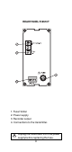
REAR PANEL HI 8710E ELECTRODE INPUT 9 8 7 3 5 PT100 + mA OUT OPEN: ACID SHORT: BASE SET 4 CONSENT 6 ALARM FUSE 1 FUSE 220 110 L 2 1. Fuse Holder 2. Power supply 3. Acid/Basic dosage selection 4. Reductant or oxidant dosage consent 5. Connections for dosing pump 6. Alarm contacts 7. Recorder output 8. Connections for PT100 temperature sensor 9. BNC socket for pH electrode. Unplug the instrument from the power supply before replacing the fuse.
REAR PANEL HI 8710T 1. Fuse Holder 2. Power supply 3. Acid/Basic dosage selection 4. Reductant or oxidant dosage consent 5. Connections for dosing pump 6. Alarm contacts 7. Recorder output 8. Connections to the transmitter. Unplug the instrument from the power supply before replacing the fuse.
FUNCTIONAL DESCRIPTION HI 8711 DUAL OUTPUT pH CONTROLLER FRONT PANEL pH HI 8711E pH SLOPE ACID SET BASE SET ∆ ∆AL MEA SURE COARSE ACID SET SENSOR TEST ∆AL FINE COARSE pH 7 TEST pH 4 TEST Keypad ACID SET BASE SET MEASURE SENSOR TEST ∆ Al BASE SET FINE HI 8711E To set the working point of acid dosage To set the working point of basic dosage To set HI 8711 on measurement mode and to enable the diagnostic tests To display the mV response of the electrode to verify its working condition.
pH 7 TEST pH 4 TEST To verify the internal circuit of the meter in terms of Offset compensation To verify the amplifier circuit of the meter Trimmers ∆O SLOPE ∆ AL For Offset calibration For Slope calibration To set the tolerance of the alarm ACID SET/COARSE To coarsely adjust the acid set point ACID SET/FINE To finely adjust the acid set point BASE SET/COARSE To coarsely adjust the basic set point BASE SET/FINE To finely adjust the basic set point Leds ACID SET (Blinking) To show the acid dosage is ac
REAR PANEL HI 8711E ELECTRODE INPUT 8 7 6 4 PT100 + mA OUT - BASE 3 ACID 5 ALARM FUSE 1 FUSE 220 110 L 2 1. Fuse Holder 2. Power supply 3. Connections for dosing pump for acid 4. Connections for dosing pump for base 5. Alarm contacts 6. Recorder output 7. Connections for PT100 temperature sensor 8. BNC socket for pH electrode. Unplug the instrument from the power supply before replacing the fuse.
REAR PANEL HI 8711T 1. Fuse Holder 2. Power supply 3. Connections for dosing pump for acid 4. Connections for dosing pump for base 5. Alarm contacts 6. Recorder output 7. Connections to the transmitter. Unplug the instrument from the power supply before replacing the fuse.
FUNCTIONAL DESCRIPTION HI 8720 ORP CONTROLLER FRONT PANEL ORP HI 8720E mV DOSAGE OXID. REDUC.
Trimmers SLOPE ∆ AL For Slope calibration To display and set the tolerance of the alarm points SET/COARSE To coarsely adjust the set point SET/FINE To finely adjust the set point Leds OXID To show the oxidant dosage is active REDUC To show the reductant dosage is active ∆AL (blinking) To show the alarm is active 21
REAR PANEL HI 8720E ELECTRODE INPUT 8 4 7 3 5 CONSENT + mA OUT OPEN: OXD SHORT: RDX SET FUSE 6 ALARM 1 FUSE 220 110 L 2 1. Fuse Holder 2. Power supply 3. Oxidant/Reductant dosage selection 4. Oxidant or reductant dosage consent 5. Connections for dosing pump 6. Alarm contacts 7. Recorder output 8. BNC socket for ORP electrode. Unplug the instrument from the power supply before replacing the fuse.
REAR PANEL HI 8720T 1. Fuse Holder 2. Power supply 3. Oxidant/Reductant dosage selection 4. Oxidant or Reductant dosage consent 5. Connections for dosing pump 6. Alarm contacts 7. Recorder output 8. Connections to the transmitter. Unplug the instrument from the power supply before replacing the fuse.
FUNCTIONAL DESCRIPTION HI 931500 SINGLE OUTPUT pH CONTROLLER FRONT PANEL e ins rum n s pH DOSAGE SLOPE ACID BASE ∆O MEA SURE SET COARSE SET FINE HI 931500 pH Process Controller Keypad SET MEASURE Trimmers ∆O SLOPE SET/COARSE SET/FINE Leds ACID BASE To set the working point of pH dosage To set HI 931500 on measurement mode For Offset calibration For Slope calibration To coarsely adjust the set point To finely adjust the set point To show the acid dosage is active To show the basic dosage is activ
REAR PANEL HI 931500 ELECTRODE INPUT 8 PT100 7 + mA OUT 6 4 5 OPEN : ACID SHORT : BASE SET CONSENT 3 FUSE FUSE 1 220 110 L 2 1. 2. 3. 4. 5. 6. 7. 8. Fuse Holder Power supply Reductant or oxidant dosage consent Acid/Basic dosage selection Connections for Dosing Pumps Recorder output Connections for PT100 temperature sensor BNC socket for pH electrode. Unplug the instrument from the power supply before replacing the fuse.
FUNCTIONAL DESCRIPTION HI 931501 DUAL OUTPUT pH CONTROLLER FRONT PANEL e ins rum n s pH DOSAGE SLOPE ACID SET BASE SET ∆O MEA SURE COARSE ACID SET FINE COARSE HI 931501 pH Process Controller BASE SET FINE Keypad ACID SET To set the working point of acid dosage BASE SET To set the working point of basic dosage MEASURE To set HI 931501 on measurement mode Trimmers For Offset calibration ∆O SLOPE For Slope calibration ACID SET/COARSE To coarsely adjust the acid set point 26
ACID SET/FINE To finely adjust the acid set point BASE SET/COARSE To coarsely adjust the basic set point BASE SET/FINE To finely adjust the basic set point Leds ACID SET (Blinking) To show the acid dosage is active BASE SET (Blinking) To show the basic dosage is active MEASURE To show the meter is on measurement mode 27
REAR PANEL HI 931501 7 ELECTRODE INPUT 6 PT100 + mA OUT - 5 4 BASE ACID FUSE 3 1 2 220 110 L FUSE 1. Fuse Holder 2. Power supply 3. Connections for dosing pump for acid 4. Connections for dosing pump for base 5. Recorder output 6. Connections for PT100 temperature sensor 7. BNC socket for pH electrode. Unplug the instrument from the power supply before replacing the fuse.
FUNCTIONAL DESCRIPTION HI 932500 ORP CONTROLLER FRONT PANEL mV DOSAGE SLOPE OXID. REDUC.
REAR PANEL HI 932500 ELECTRODE INPUT 7 3 6 4 5 CONSENT + mA OUT OPEN: OXD SHORT: RDX SET FUSE 1 FUSE 220 110 L 2 1. Fuse Holder 2. Power supply 3. Oxidant or reductant dosage consent 4. Oxidant/Reductant dosage selection 5. Connections for dosing pump 6. Recorder output 7. BNC socket for ORP electrode. Unplug the instrument from the power supply before replacing the fuse.
SPECIFICATIONS HI 8510 HI 8510E HI 8510T 0.00 to 14.00 pH Range Resolution 0.01 pH Accuracy ±0.02 pH ±0.5% Typical EMC Deviation ±0.1 pH ±0.2 mA ±0.1 pH ±0.2 mA Installation Cat.
SPECIFICATIONS HI 8710 HI 8710E HI 8710T 0.00 to 14.00 pH 0.01 pH ±0.02 pH ±0.5% ±0.1 pH ±0.1 pH ±0.2 mA ±0.2 mA II 1012 Ohm 4 to 20 mA Offset: ±2 pH ∆O trimmer Slope: 80 to 110% Slope trimmer Temperature Fixed or automatic with PT100 Compensation from 0 to 100°C Set Point Relay One, Isolated, 2 A, max 240 V, resistive load, 1.000.000 strokes Alarm Relay One, Isolated, 2 A, max 240 V, resistive load, 1.000.
SPECIFICATIONS HI 8720 HI 8720E Range HI 8720T -1000 to +1000 mV Resolution Accuracy Typical EMC Deviation 1 mV ±5 mV ±0.5% ±6 mV ±0.2 mA ±6 mV ±0.2 mA Installation Cat. II 1012 Ohm Input Calibration 4 to 20 mA Slope: 90 to 110% Slope trimmer Set Point Relay One, Isolated, 2 A, max 240 V, resistive load, 1.000.000 strokes Alarm Relay One, Isolated, 2 A, max 240 V, resistive load, 1.000.
SPECIFICATIONS HI 931501 Range Resolution Accuracy Typical EMC Deviation Installation Cat. HI 931501 0.00 to 14.00 pH 0.01 pH ±0.02 pH ±0.1 pH ±0.2 mA II 1012 Ohm Offset: ±2 pH ∆O trimmer Slope: 80 to 110% Slope trimmer Temperature Fixed or automatic with PT100 Compensation from 0 to 100°C Readout 4-digit LCD plus graphic symbols Recorder Output 0 to 20 mA or 4 to 20 mA Set Point Relay Two, Isolated, 2 A, max 240 V, resistive load, 1.000.
• • • • • Connect a 3-wire power cable to the 4-screw terminal strip; according to the voltage level as indicated and pay particular attention to the correct live, earth and neutral terminal connections. For Model E, HI 931500, HI 931501 and HI 931500 connect the pH or ORP electrode to the BNC marked "ELECTRODE INPUT". For Model T, connect the 2 signal wires of the pH or ORP transmitter to the terminal marked "IN/OUT TRANSMITTER" paying particular attention to the indicated polarity.
• HI 8710 and HI 931500 are single dosage controllers for dosing either acid or alkaline liquid. If you plan to dose acid (e.g. in Hexavalent Chromium reduction), make an open circuit between ACID/BASE selection terminals (see rear panel descriptions #3 at page 12-13 and #4 at page 23). If you plan to dose alkaline (e.g. in Cyanide oxidation product), make a short circuit across the above mentioned terminals. HI 8720 and HI 932500 are single dosage controllers for dosing either oxidant or reductant liquid.
• Acid Contacts (HI 8711 and HI 931501 only): these two contacts are for the connection to the dosing pump for the acid. They act as a switch for the power to the drive. • Base contact (HI 8711 and HI 931501 only): these two contacts are for the connection to the dosing pump for the base. They act as a switch for the power to the drive.
OPERATIONAL GUIDE The setting of the various keys are made via the front panel keys and trimmers. When each key is pressed the LED is lighted indicating to the user that the function is in operation. Make sure that the pH or the ORP meter with the electrode is calibrated before operating the instruments (see page 40-42). SET POINTS HI 8710, HI 8720, HI 931500 and HI 932500 only To set the working point of pH or ORP dosage, press the "SET" key. The display will show the set value.
Use a small screwdriver to adjust the trimmers "ACID SET"/"COARSE" and "FINE" until the desired base set value is displayed. ACID SET BASE SET pH COARSE ACID SET FINE To set the working point of base dosage, press the "BASE SET" key. The display will show the set value for base dosage. ACID SET BASE SET pH COARSE BASE SET FINE Use a small screwdriver to adjust the trimmers "BASE SET"/"COARSE" and "FINE" until the desired base set value is displayed.
Use a small screwdriver to adjust the trimmers "∆AL" until the desired tolerance is displayed. ∆AL ∆AL pH For example: in HI 8710 if the set value is pH 3 and a ∆ Alarm of 1.5 pH is chosen, the instrument gives an alarm every time the measured pH value is higher than 4.5 pH or lower than 1.5 pH. In HI 8711 if the set values are pH 7 and pH 8 and a ∆ Alarm of 1.5 pH is chosen, the instrument gives an alarm every time the measured pH value is higher than 9.5 pH or lower than 5.5 pH.
When acid is dosed, the ACID LED will be lighted, and when base is being dosed, the BASE LED will be lighted (HI 8710, HI 931500 and HI 931501 only). When oxidants are dosed, the OXID LED will be lighted, and when reductants are being dosed, the REDUC LED will be lighted (HI 8720, HI 932500 only). 41 DOSAGE ACID BASE MEA SURE SET SLOPE ∆AL COARSE SET FINE DOSAGE OXID. REDUC.
pH CALIBRATION Make sure you are in the measurement mode (MEASURE LED light is on) and not in the set mode before proceeding the calibration (not for HI 8510). MEA SURE COARSE SET FINE Note the temperature of the buffer with a ChecktempC or a glass thermometer. °C 4 cm (1½") Remove the protective cap from the electrode, rinse it with some pH 7.01 solution (HI 7007), then dip in pH 7.01 buffer. Note: the electrode should be submerged approximately 4 cm (1½") into the solution.
Note: to get accurate readings, use pH 4.01 if you are going to measure acid samples or pH 10.01 for alkaline measurements. Shake briefly and wait one minute before adjusting the slope trimmer to display pH 4.01 (or 10.01) on the LCD if the temperature of the buffer solution is at 25°C, if not refer to the chart on page 43 for appropriate buffer value for the corresponding temperature.
pH VALUES AT VARIOUS TEMPERATURE Temperature has an effect on pH. The calibration buffer solutions are effected by temperature changes to a lesser degree than normal solutions. Please refer to the following chart to perform the pH calibration: TEMP °C °F 4.01 6.86 0 5 10 15 20 25 30 35 40 45 50 55 60 65 70 4.01 4.00 4.00 4.00 4.00 4.01 4.02 4.03 4.04 4.05 4.06 4.07 4.09 4.11 4.12 6.98 6.95 6.92 6.90 6.88 6.86 6.85 6.84 6.84 6.83 6.83 6.84 6.84 6.85 6.
pH DIAGNOSTIC TESTS The HI 8510, HI 8710 and HI 8711 are the only pH controllers with built-in autodiagnostic functions to enable the user to check and troubleshoot any malfunctions. The functions are made via front panel keys to isolate the cause of malfunction whether it is due to pH electrode contamination, internal offset circuit or the amplifier circuit. Follow the procedure describe below if you detect any malfunctioning of the instrument or electrode.
B) Internal Offset Circuit Test Press the "pH7 TEST" key and the display should show a value between 7 pH ±1 pH. This will verify the internal circuit of the meter in terms of the offset compensation. pH 7 TEST pH C) Amplifier Circuit Test Press the "pH4 TEST" key and the display should show a value between 3.30 pH and 4.30 pH. This will verify the amplifier circuit of the meter.
ORP DIAGNOSTIC TESTS The HI 8512 and HI 8720 are the only ORP controllers with built-in autodiagnostic functions to enable the user to check and troubleshoot any malfunctions. The functions are made via front panel keys to isolate the cause of malfunction. Press the "MEASURE" key before proceeding with the following tests (HI 8720 only). A) B) 0 mV Test Press the "0 mV TEST" key and the display should show a value of 0 mV ±10 mV. This will verify instrument calibration at point 0.
LED INDICATION The LEDs above all keys are designed to indicate the state of each function, whether it is active or the display is indicating the mode. For HI 8711 and HI 931501 only Each LED can be in one of the following states: A) Light stays on The mode is displayed on the LCD but is not active. E.g. alarm set point is displayed but the alarm contact is open. B) Light Blinking 25% On, 75% Off The mode is not displayed on the LCD but the mode is active. E.g.
TAKING REDOX MEASUREMENTS Redox measurements allow the quantification of the oxidizing or reducing power of a solution, and are commonly expressed in mV. Oxidation may be defined as the process during which a molecule (or an ion) loses electrons and reduction as the process by which electrons are gained. Oxidation is always coupled together with reduction so that as one element gets oxidized, the other is automatically reduced, therefore the term oxidation-reduction is frequently used.
To make correct redox measurements the following conditions must prevail: - The surface of the electrode must be cleaned and smooth. - The surface of the electrode must undergo a preventive treatment depending on the solution to be measured has oxidizing or reductive characteristics. Because the Pt/PtO system depends on the pH, the pretreatment of the electrode may be determined by the pH and the redox potential of the solution to be measured.
In the event that measurements are performed with solutions containing sulfides or proteins, the cleaning of the diaphragm of the reference electrode must be performed (see page 20, "Cleaning Procedure"). In order to have a correct functioning of the ORP electrode, immerse it into HI 7020 and measure the response; the obtained value should be within 200 and 275 mV.
ELECTRODE CONDITIONING AND MAINTENANCE Reference Filling Hole Reference Filling Hole Fill Hole Screw Sensitive Wire Reference Wire Reference Wire Sensitive Wire Reference Junction Reference Junction Glass Bulb Glass Bulb Plastic Body pH Electrode Reference Wire Reference Junction Platinum or Gold tip Glass Body pH Electrode Reference Wire Plastic Body ORP Electrode Reference Junction Platinum or Gold tip Glass Body ORP Electrode PREPARATION Remove the protective cap.
cannot function properly under these conditions. These bubbles can be removed by "shaking down" the electrode as you would do with a glass thermometer. If the bulb and/or junction are dry, soak the electrode in HI70300 Storage Solution for at least one hour. For refillable electrodes: If the fill solution (electrolyte) is more than 1 cm (½") below the fill hole, add HI 7082 3,5M KCl Electrolyte Solution for double junction or HI 7071 3,5M KCl+AgCl Electrolyte Solution for single junction electrodes.
Follow the Preparation Procedure above before taking measurements. Note: NEVER STORE THE ELECTRODE IN DISTILLED WATER OR DRY. PERIODIC MAINTENANCE Inspect the electrode and the cable. The cable used for the connection to the meter must be intact and there must be no points of broken insulation on the cable or cracks on the electrode stem or bulb. Connectors must be perfectly clean and dry. If any scratches or cracks are present, replace the electrode. Rinse off any salt deposits with water.
IMPORTANT: After performing any of the cleaning procedures rinse the electrode thoroughly with distilled water, drain and refill the reference chamber with fresh electrolyte, (not necessary for GEL filled electrodes) and soak the electrode in HI 70300 or HI 80300 Storage Solution for at least 1 hour before taking measurements. TROUBLESHOOTING Evaluate your electrode performance based on the following.
and then follow the Cleaning Procedure above. • For ORP Electrodes: polish the metal tip with a light abrasive paper (paying attention not to scratch the surface) and wash thoroughly with water.
SUGGESTED INSTALLATIONS SHORT DISTANCE, INDOOR INSTALLATION Due to the low current involved, a very high grade of insulation is required. A dry environment is needed in order to obtain a level of insulation not lower than 1012 Ω.
installed without special connectors. MAXIMUM 50 METERS WET ENVIRONMENT RELATIVE HUMIDITY UP TO 100% pH-ORP pHMETER METER WITH AN AmpHel ® ELECTRODE MEASUREMENTS CAN BE TAKEN FROM DISTANCES UP TO 50 METERS (165 FEET) AmpHel® electrodes have a micro-amplifier in the electrode cap to boost the signal, drastically reducing susceptibility to noise and drift. With all of the components sealed in the electrode body, moisture up to 100% RH will not effect the signal.
ACCESSORIES pH CALIBRATION SOLUTIONS HI7004M pH 4.01 Buffer Solution, 230 mL HI7004L pH 4.01 Buffer Solution, 460 mL HI7006M pH 6.86 Buffer Solution, 230 mL HI7006L pH 6.86 Buffer Solution, 460 mL HI7007M pH 7.01 Buffer Solution, 230 mL HI7007L pH 7.01 Buffer Solution, 460 mL HI7009M pH 9.18 Buffer Solution, 230 mL HI7009L pH 9.18 Buffer Solution, 460 mL HI7010M pH 10.01 Buffer Solution, 230 mL HI7010L pH 10.
pH ELECTRODES HI 1090T Screwcap PG13.5 connector, double junction, glass-body PG13.5 THREAD φ 12mm 30mm φ 9.5mm 110mm HI 1110S Screw connector, single junction, glass-body HI 1130B/3 BNC connector, 3 m (9.9') cable, single junction, glass-body M13 x 1.5 DIA 16 mm DIA 9.5mm DIA 12mm 3/4 x 16 UNF DIA 20.5mm 25 7 mm mm 38.5mm 110mm HI 1110S HI 1130B/3 HI 1110T Screwcap PG13.5 connector, double junction, glass-body PG13.5 THREAD φ 12mm 30mm φ 9.
HI 1210T Screwcap PG13.5 connector, double junction, plastic-body PG13.5 THREAD φ 12mm 30mm HI 1910B 110mm BNC connector, 1 m (3.3') cable, double junction, plastic-body, built-in amplifier 3/4 x 16 UNF DIA 12mm DIA 20.5mm 38.5mm HI 1911B 110mm BNC connector, 1 m (3.3') cable, double junction, plastic-body, built-in amplifier 3/4 x 16 UNF DIA 12mm DIA 20.5mm 38.5mm 110mm HI 1912B BNC connector, 1 m (3.
HI 2910B/5 BNC connector, 5 m (16.5') cable, double junction, plastic-body, built-in amplifier 3/4 x 16 UNF DIA 12mm DIA 20.5mm 38.5mm 110mm ORP ELECTRODES HI 2930B/5 BNC connector, 5 m (16.5') cable, Pt, Ultem®-body, built-in amplifier 3/4 x 16 UNF DIA 12mm DIA 20.5mm 38.5mm 110mm HI 3110S Screw-type connector, Pt, glassbody HI 3130B/3 BNC connector, 3 m (9.9') cable, Pt, glass-body M13 x 1.5 DIA 16 mm 3/4 x 16 UNF DIA 12mm DIA 20.5mm 25 7 mm mm 38.
HI 3210T Screwcap PG13.5 connector, Pt, plastic-body PG13.5 THREAD φ 12mm 30mm 110mm HI 3410S Screw connector, Pt, plastic-body HI 3430B/3 BNC connector, 3 m (9.9') cable, Pt, plastic-body 3/4 x 16 UNF M13 x 1.5 DIA 16 mm DIA 12mm DIA 20.5mm 25 7 mm mm 38.5mm 110mm HI 3410S HI 3430B/3 HI 3932B/5 BNC connector, 5 m (16.5') cable, Pt, Ultem®-body, built-in amplifier 3/4 x 16 UNF DIA 12mm DIA 20.5mm 38.5mm 110mm HI 4110S Screw-type connector, Au, glassbody HI 4130B/3 BNC connector, 3 m (9.
OTHER ACCESSORIES ChecktempC Pocket-size thermometer with penetration probe and 0.1°C resolution (range -50.0 to 150.0°C) HI 76501/P HI 8614 HI 8614L HI 8615 HI 8615L BL PUMPS HI 7871 & HI 7873 HI 6050 & HI 6051 HI 6054 & HI 6057 HI 778P Calibration Screwdriver (20 pcs) pH Transmitter pH Transmitter with LCD Display ORP Transmitter ORP Transmitter with LCD Display Dosing Pumps with Flow Rate from 1.
WARRANTY All Hanna Instruments meters are warranted for two years against defects in workmanship and materials when used for their intended purpose and maintained according to instructions. The probes and the electrodes are warranted for a period of six months. Damages due to accident, misuse, tampering or lack of prescribed maintenance are not covered. This warranty is limited to repair or replacement free of charge. If service is required, contact the dealer from whom you purchased the instrument.
CE DECLARATION OF CONFORMITY DECLARATION OF CONFORMITY We Hanna Instruments Srl V.
HANNA LITERATURE Hanna publishes a wide range of catalogs and handbooks for an equally wide range of applications. The reference literature currently covers areas such as: • Water Treatment • Process • Swimming Pools • Agriculture • Food • Laboratory • Thermometry and many others. New reference material is constantly being added to the library. For these and other catalogs, handbooks and leaflets, contact your dealer or the Hanna Customer Service nearest to you.
MANPROCR2 01/02 h t t p : / / w w w . h a n n a i n s t .