Instruction Manual HI 8410 Dissolved Oxygen Process Controller w w w . h a n n a i n s t .
Dear Customer, Thank you for choosing a HANNA instruments® product. Please read this instruction manual carefully before using the instrument. This manual will provide you with all the necessary information for correct use of the instruments, as well as a precise idea of thier versatility in a wide range of applications. If you need additional technical information, do not hesitate to e-mail us at tech@hannainst.com. TABLE OF CONTENTS Preliminary Examination ................................................
PRELIMINARY EXAMINATION Remove the instrument from the packing material and examine it carefully to make sure that no damage has occurred during shipping. If there is any damage, notify your dealer. The meter is supplied complete with • Mounting brackets • Transport splash-proof cover • Instructions manual. Note: Conserve all packing material until the instrument has been observed to function correctly. Any defective item must be returned in its original packing.
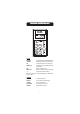
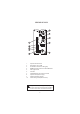
FUNCTIONAL DESCRIPTION HHII 8410 KEYPAD MEASURE ΔALARM SET SALINITY g/L To read measurements and enable diagnostic tests To display and set the tolerance of the alarm To display and set the working dosing point To display and set the salinity factor (active only in mg/L range) CAL To enter in calibration mode 100% TEST Diagnostic function (active only in % DO range) °C To display the temperature reading When a key is pressed, the corresponding LED lights up to indicate that the function is active.
LEDS % DO To indicate that the DO is displayed in % of saturation mg/L To indicate that the DO is displayed in mg/L SET To indicate that the dosage is active ΔALARM To indicate an alarm condition DOSAGE MODE SWITCH To indicate that the continuous ON or OFF mode is selected from dosing switch SWITCHES OFF/AUTO/ON To select the dosing mode: • OFF - dosing is disabled • AUTO - automatic dosage, depending on setpoint and reading values • ON - dosing always active 5
REAR PANEL OF HI 8410 1. 2. 3. 4. 5. 6. 7. 8. 9. 10. DO probe connection terminals Range selection: mg/L or % DO SET terminals for connection to a dosing pump ALARM terminals for connection to an external alarm device Power supply terminals Fuse holder mA OUTPUT terminals for connection to a recorder Hysteresis set knob (0.5 to 2.4 mg/L) Disable overtime dosing connection Overtime dosing set knob (about 5 to 60 min) Unplug the instrument from power supply before replacing the fuse.
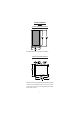
MECHANICAL DIMENSIONS OF HI 8410 Front view of the panel-mounted unit These dimensions show the cutout size for the installation. Side view of the panel-mounted unit Adjustable location brackets (supplied with the meter) allow the indicator to slide into the cutout and will hold the unit securely in place. 190 mm (7.50") is the minimum amount of room required to install the indicator with the cables connected.
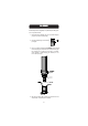
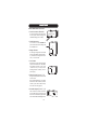
D.O. PROBES All Hanna DO probes are shipped dry. To hydrate the probe and prepare it for use proceed as follows: 1. Remove the black & red plastic cap. This cap is used for shipping purposes only and can be thrown away. 2. Insert the supplied O-ring in the membrane (see figure). 3. Rinse the supplied membrane (HI 76409A/P) with electrolyte while shaking it gently. Refill with clean electrolyte. Gently tap the membrane over a surface to ensure that no air bubbles remain trapped.
SPECIFICATIONS HHII 8410 Range 0.0 to 50.0 mg/L (ppm) O2 0 to 600 % O2 -5.0 to 50.0 °C Resolution 0.1 mg/L or 1% (O2) / 0.1 °C Accuracy Calibration ±1% of reading (O2) ±0.2 °C excluding probe error Manual, one point, in saturated air Temp.
CONNECTIONS REAR CONNECTIONS FOR HI 8410 • Power Connection Terminals 4-screw-terminal-strip for connection to a 3-wire power cable according to the indicated voltage (115 or 230V). • Probe Connection For connection of the HI76409 DO probe. Connect the wires according with the indicated color. • Range Selection To select mg/L range make a short with a jumper wire between the terminals (1, 2). To select % DO range leave terminals 1, 2 unconnected.
Connect the “+” wire from the recorder to terminal 1 on the instrument and the other wire (common) to terminal 2 for 4-20 mA recorder output or terminal 3 for 0-20 mA recorder output. Note: Only one recorder output connection is permited. In order to avoid malfunction leave unconnected the unused terminal. • Overtime dosing When enabled this feature ensures that overdosage is avoided. Select a desired maximum dosage period.
AUTO mode The dosage is activated and deactivated according with the selected setpoint. The corresponding DOSAGE MODE LED is off. Be sure that the DOSAGE switch is in AUTO position when the meter is in normal operating mode. ON mode The dosage is always activated. The corresponding DOSAGE MODE LED blinks. OPERATIONAL GUIDE INITIAL PREPARATION & INSTALLATION Material needed: • a 3-wire power cable to connect HI 8410 Ensure the controller has been calibrated.
Ensure that the HI 76409 DO probe is connected to the meter according with the colors indicated on the mask. OPERATING INFORMATION All parameters are set through the front panel keys and trimmers. When any key is pressed, the corresponding LED lights up to indicate that the function is active. SET POINT To set the working point of the controller, press the SET key. The display will indicate the current set value.
Press the SALINITY g/L and the display will show the salinity. Use a small screw driver to adjust the SALINITY trimmer to display the desired salinity value (within the 0 to 51 g/L range). ALTITUDE COMPENSATION (mg/L range only) When salinity compensation is not required (i.e. not salty water), the SALINITY trimmer can be used to set the altitude correction value. Enter the mg/L mode. Press the SALINITY g/L button.
The alarm contacts of HI 8410 remain closed during normal operation. If the measured conductivity level is not within the tolerance of the set value, the alarm contact will be open. HYSTERESIS SET Turn the hysteresis knob (rear panel) in the desired position (from 0.5 to 2.4 mg/L range). The dosage will be active according to the DO reading set point value and hysteresis set value.
CALIBRATION PROCEDURE Calibration is a very simple 1-point procedure, performed in air, only in % DO range. Ensure the probe is ready for measurements, i.e. the membrane is filled with electrolyte (see “Probe Preparation” section for details). If the instrument is set on the % DO range (the mg/L range selection switch on the rear panel is open) simply turn the CAL trimmer to display 100%.
LED INDICATION All LEDs above the keys or near switches indicate the state of each function, whether it is active or the display is indicating the mode. % DO LED It is on if the selected range is % DO. mg/L LED It is on if the selected range is mg/L.. OFF/AUTO/ON LED It is on when the switch is in OFF (dosage disabled) or in ON (dosage continuous enabled) position. SET LED In MEASURE mode it is OFF or blinking (25% ON) in accordance with the dosage relay status (inactive/ active).
PROBE MAINTENANCE & CLEANING For a top performance probe, it is recommended to replace the membrane every 2 months and the electrolyte once a month. Proceed as follows: • Unscrew the membrane by turning it counterclockwise. • Rinse the supplied spare membrane (HI 76409A/P) with some electrolyte solution while shaking it gently. Refill with clean electrolyte. • Gently tap the membrane over a surface to ensure that no air bubbles remain trapped.
WARRANTY All HANNA instruments® meters are warranted for two years against defects in workmanship and materials when used for their intended purpose and maintained according to instructions. The probes are warranted for a period of one year. This warranty is limited to repair or replacement free of charge. Damages due to accident, misuse, tampering or lack of prescribed maintenance are not covered. If service is required, contact the dealer from whom you purchased the instrument.
Hanna Instruments Inc. Highland Industrial Park 584 Park East Drive Woonsocket, RI 02895 USA Local Sales and Customer Service office Hanna Instruments United States Inc. Highland Industrial Park 584 Park East Drive Woonsocket, RI 02895 USA Tel. (800) 426 6287 Fax (401) 765 7575 www.hannainst.com/usa Technical Support for customers Telephone (800) 426 6287 Fax (401) 765 7575 E-mail tech@hannainst.