Instruction Manual HI 83414 Turbidity and Free/Total Chlorine Meter w w w. h a n n a i n s t .
Dear Customer, Thank you for choosing a Hanna Instruments product. Please read this instruction manual carefully before using this instrument. This manual will provide you with the necessary information for correct use of this instrument, as well as a precise idea of its versatility. If you need additional technical information, do not hesitate to e-mail us at tech@hannainst.com or view our worldwide contact list at www.hannainst.com.
TABLE OF CONTENTS WARRANTY .......................................................................................................................... 2 PRELIMINARY EXAMINATION................................................................................................. 4 GENERAL DESCRIPTION ........................................................................................................ 5 ABBREVIATIONS ................................................................................................
PRELIMINARY EXAMINATION Please examine this product carefully. Make sure that the instrument is not damaged. If any damage occurred during shipment, please notify your local Hanna Office.
GENERAL DESCRIPTION GENERAL DESCRIPTION HI 83414 is a high accuracy, combined meter with technology that benefits from Hanna’s years of experience as manufacturer of analytical instruments. The HI 83414 successfully combines turbidity and colorimetric measurements to meet the needs of measuring the most important parameters of drinking water: turbidity and free/total chlorine.
ABBREVIATIONS NTU JTU FTU USEPA LCD Nephelometric Turbidity Units Jackson Turbidity Units Formazin Turbidity Units US Environmental Protection Agency Liquid Crystal Display RTC RH ID EBC Real Time Clock Relative Humidity Identification European Brewery Convention PRINCIPLE OF OPERATION TURBIDIMETER Turbidity is the optical property that causes light to be scattered and absorbed, rather than transmitted. The scattering of the light that passes through a liquid is primarily caused by the suspended solids.
For the ratio turbidimeter range, the microprocessor of the instrument calculates the NTU value, from the signals that reach the two detectors, by using an effective algorithm. This algorithm corrects and compensates for interferences of color, making the HI 83414 instrument color-compensated. The optical system and measuring technique compensate also for the lamp intensity fluctuations, minimizing the need of frequent calibration.
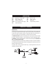
Where: –log I/Io = Io = I = ελ = c = d = Absorbance (A) intensity of incident light beam intensity of light beam after absorption molar extinction coefficient at wavelength λ molar concentration of the substance optical path through the substance Therefore, the concentration “c” can be calculated from the absorbance of the substance as the other factors are known.
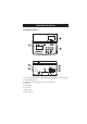
FUNCTIONAL DESCRIPTION INSTRUMENT DESCRIPTION 1) 2) 3) 4) 5) 6) 7) 8) Liquid Crystal Display (LCD). The LCD has backlight for better visibility in dark environments. Keypad. Splash resistant. Cuvette Lid. Close the cuvette lid prior to start a measurement.
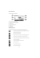
DISPLAY DESCRIPTION The display contains the following fields: 1 1) 2) 3) 4) 5) 6) 6 2 5 3 4 The current time in selected format Information related to the measurement Functional keys Currently selected parameter Measuring units Measured value KEYBOARD DESCRIPTION The keyboard contains 8 direct keys and 3 functional keys with the following functions: The function of each of the three functional keys depends on the name displayed on the LCD above them. ESC RANGE Press to return to the main screen.
SPECIFICATIONS Turbidity Range - non ratio mode Resolution - non ratio mode Range - ratio mode Resolution - ratio mode Range selection Accuracy Repeatibility Stray Light Light Detector Method Measuring mode Turbidity Standards Calibration 0.00 to 9.99; 10.0 to 40.0 NTU 0.0 to 99.9; 100 to 268 Nephelos 0.00 to 9.80 EBC 0.01; 0.1 NTU 0.1; 1 Nephelos 0.01 EBC 0.00 to 9.99; 10.0 to 99.9; 100 to 4000 NTU 0.0 to 99.9; 100 to 26800 Nephelos 0.00 to 9.99; 10.0 to 99.9; 100 to 980 EBC 0.01; 0.1; 1 NTU 0.
Standards Calibration 1 mg/L free chlorine, 1 mg/L total chlorine One-point calibration Other Light Source Lamp life Display LOG Memory Serial Interface Environment Power supply Auto Shut-off Dimensions Weight Tungsten filament lamp greater than 100,000 readings 40 x 70 mm graphic LCD (64 x 128 pixels) with backlight 200 records USB 0 °C (32 °F) to 50 °C (122 °F); max 95% RH non-condensing 230 V/50 Hz or 115 V/60 Hz 20 W After 15 minutes of non-use 230 x 200 x 145 mm (9 x 7.9 x 5.7”) L x W x H 2.
Note: In colorimetric measurements, when it is possible, use the same cuvette both for zeroing and measurement. If this is not possible, always match the cuvettes. In turbidimetric measurements, if you are using multiple cuvettes, always match the cuvettes. CUVETTE HANDLING The cuvettes should be free of scratches or cracks. Any cuvette with visible scratches should be discarded. The cuvettes should be periodically washed with acid.
Note: The supplied cloth for oiling should be stored together with the silicone oil bottle and cuvettes, taking care to avoid contamination with dirt. After a few oiling procedures, the cloth will contain enough oil to wipe the bottle with it without adding more oil. From time to time add some drops of oil on the cuvette to provide the necessary oil quantity in the cloth.
• Insert the cuvette into the instrument and press the Read key. Record the reading. • Open the instrument lid, slightly rotate the cuvette and take a new reading. • Repeat the last step until you read the lowest NTU value. • Alternatively, keep the Read key pressed to make continuous readings. After the first value is displayed, open the lid and start rotating the cuvette until the lowest NTU value is displayed.
• Turn the instrument ON. • Insert the first cuvette into the instrument and press the Read key. Record the reading. • Mark this position on the thicker white band on the top of the cuvette with a water resistant pencil. • Insert the second cuvette into the instrument and take a reading. • Open the instrument lid, slightly rotate the cuvette and take a new reading. • Repeat the last step for the second cuvette until the reading is within 0.01 NTU of the value obtained for the first cuvette.
• Alternatively, keep the Read key pressed and, after the first value is displayed, open the lid and start rotating the cuvette until the read value matches the first cuvette. • Mark this position on the second cuvette with a water resistant pencil. • Follow the same procedure for all the cuvettes you need. Note: If the cuvette is indexed, use the index to position it in the instrument. SAMPLING TECHNIQUE When taking turbidity measurements it is very important to select a representative sample.
ADDITION OF SURFACTANT A surfactant addition works by changing the surface tension of the water. In this way bubbles are released from the sample. This method is effective in samples that are supersaturated with air. The procedure consists in the addition of a drop of surfactant in the cuvette before adding the sample to be analyzed. A convenient surfactant to use for degassing is Triton X-100. Warning: Changing the surface tension will cause a rapid settling of particles that cause turbidity.
ADDING REAGENT (COLORIMETRY only) • Because the reagent quantity is set up to react with 10 mL of sample, it is very important to fill the cuvette correctly. The liquid in the cuvette forms a meniscus; the bottom of the meniscus must be at the same level with as the 10 mL mark.
START UP The HI 83414 Turbidity / Free & Total Chlorine benchmeter is supplied with all necessary accesories for making measurements. Unpack the instrument and place it on a flat surface. Do not place the instrument under direct sunlight. Connect the instrument to the mains with the provided power cord. Pay attention that the mains voltage match the value printed on the back of the instrument. Switch on the instrument.
TUTORIAL MODE The HI 83414 has a unique Tutorial Mode that provides additional information to help the inexperienced user during the measurements. The instruments display a screen, with explanations and confirmation button, each time when a preparation or other operation has to be performed by the operator. The instrument resumes the measuring sequence when the operator confirms that the requested operation was done.
MEASUREMENT PROCEDURE FOR RATIO / NON RATIO TURBIDITY RANGE When taking turbidity measurements, several basic rules should be followed: • Never use cuvettes with scratches or cracks because they can cause inaccurate readings. • Always cap the cuvettes to avoid spillage of the sample into the instrument. • Always close the lid of the instrument during measurement. • Do not use too much oil to prevent contamination of the optical system.
NORMAL MEASUREMENT This type of measurement is best suited for regular readings, when the sample is stable and normal accuracy is required. In normal mode, the measurement takes about 10 seconds and the lamp is ON for a minimum period of time (about 7 seconds). • Press the Read key to take the measurement. The display will show “READ” in the left side and blinking dashes. The dashes and lamp icon will appear during different measurement phases. • The result is displayed in the selected units.
averaged value remains on the display at the end of the measurement. HI 83414 automatically selects the correct turbidity range to display the results with the highest accuracy. If the measured value is higher than 4000 NTU (980 EBC or 26800 Nephelos), the display will show the maximum value blinking and the message “Out of range” on the message line. UNITS CHANGE To change the units, simply press the Unit key when a measurement is available. The Nephelos value is obtained by multiply with 6.
CALIBRATION PROCEDURE FOR RATIO / NON RATIO TURBIDITY RANGE HI 83414 has a powerful calibration function that compensates for lamp aging or changing. The calibration can be done using the supplied calibration solutions or user prepared standards. HI 83414 turbidimeter is supplied with 5 AMCO standards: <0.1 NTU, 15 NTU, 100, 750 NTU and 2000 NTU. The Hanna standards are specially designed for this instrument. Turbidity standards have a shelf life and should not be used after the expiration date.
To enter calibration, press the CAL CHECK key while in main screen. The first screen of GLP information is displayed. Press the Cal key to start calibration. It is possible to interupt calibration procedure at any time by pressing the CAL CHECK key . TWO-POINT CALIBRATION (Ratio and Non Ratio Turbidity) • The first calibration point is displayed on the LCD as 0.00 NTU. This point is used to check the quality of the water used for dilution and to confirm that the optical system is not dirty.
• Close the lid and press the Read key. The display will show the value blinking and the lamp icon during measurement. • If Non ratio Turbidity range is selected, the display will briefly show “Store...” and the two point calibration is saved. The instrument returns in the main screen. • If Ratio Turbidity range is selected, at the end of the measurement, the third proposed calibration point (100 NTU) is displayed. • At this moment it is possible to exit calibration by pressing the End key.
• Close the lid and press the Read key. The display will show the value blinking and the lamp icon during measurement. • At the end of the measurement, the fifth proposed calibration point (2000 NTU) is displayed. • At this time it is possible to exit calibration by pressing the End key. • If the calibration is terminated, the display will briefly show “Store...” and the four point calibration is saved. The instrument returns in the main screen.
OUT OF CAL RANGE FUNCTION The instrument has a mechanism to prevent taking measurements in a range where the calibration does not assure the best results. The message “Out of Calibration Range” is displayed on the message line in the following situations: • When the first calibration point is over 0.15 NTU and the reading is under 10 NTU. • When two point calibration was performed and the reading value is over 40 NTU.
• Place the cuvette into the instrument. Align the mark on the cuvette with the sign on the instrument top and close the lid. • Press the Zero key. The dashes and the lamp icon will blink on the LCD, depending on the measurement phase. If the zeroing procedure was successful, the display will show “-0.0-”. SINGLE SAMPLE READ • Remove the cuvette from the instrument. • Remove the cap.
• Press the Timer key. The display will show the stopwatch icon and the countdown prior to measurement. Alternatively wait for: Free Chlorine Total Chlorine 1 minute or 2 minutes and 30 seconds and then just press the Read key. Dashes and the lamp icon will blink on the LCD, depending on the measurement phase. The instrument then displays the concentration in mg/L of free or total chlorine. Note: If the value is over range, the maximum value (5.
Note: It is recommended to zero the meter before each measurement. INTERFERENCES The colorimetric measurements are affected by the following interfering agents: • Bromine (positive error). • Chlorine dioxide (positive error). • Iodine (positive error). • Oxidized Manganese and Chromium (positive error). • Alkalinity above 250 mg/L CaCO3 or acidity above 150 mg/L CaCO3 will not reliably develop the full amount of color or it may rapidly fade. To resolve this, neutralize the sample with diluted HCl or NaOH.
• Place the zero cuvette (A) in the instrument with the mark aligned with the mark on the instrument top. • Close the lid • Press the Zero key. The dashes and the lamp icon will blink on the LCD, depending on the measurement phase. If the zeroing procedure was successful, the display will show “-0.0-”. • Remove the cuvette. • Place the CAL CHECK™ Standard cuvette B into the holder. Make sure that the mark on the glass is aligned with the mark on the instrument top. • Press the Chk key.
CALIBRATION PROCEDURE FOR FREE/TOTAL CHLORINE Use the provided standard solution to calibrate the free or total chlorine range of the HI 83414. Do not calibrate the instrument with standard solutions other than Hanna CAL CHECK™ Standards, otherwise erroneous results will be obtained. For accurate calibration please perform test at room temperature, 18 to 25 ºC (64.5 to 77.0 ºF). To calibrate one range, follow next steps: • Turn the instrument on by toggling ON/OFF.
CALIBRATION ERROR MESSAGES • The calibration is successfully performed if the reading is in certain limits. If the CAL CHECK™ standard value is too high, the display will show a high standard message. If this message appears, check if the correct cuvette was used. • If the CAL CHECK™ standard value is too low, the display will show low standard message. If this message appears, check if the correct cuvette was used.
GOOD LABORATORY PRACTICE (GLP) The HI 83414 has built in complete GLP information. The calibration date and the calibration points are displayed in a comprehensive mode for each range. To display the GLP information, simply press CAL CHECK key. A screen with instrument serial number and with information about the calibration is displayed. For further information, press the GLP key.
LOG AND LOG RECALL The HI 83414 has a powerful log function that could store up to 200 records. Each record contains: • the measuring range, • the reading value, • the measuring units, • the date and time of the measurement, • the current log number. Notes: • The logs for each parameter are mixed together. The records are arranged based on the record time. • The log can be saved only after a measurement is completed. • A measurement can be saved only once.
SETUP In the Setup mode, the instrument’s parameters can be changed. Some parameters affect the measuring sequence and others are general parameters that change the behaviour or appearence of the instrument. The items that are related to the selected parameter do not appear in the setup when another parameter is selected. The setup mode may be accessed from the main screen by pressing the SETUP key. Press ESC or SETUP to return to the main screen.
Date / Time This option is used to set the instrument’s date and time. Press the Modify key to change the date/time. Press the ⊳ u functional keys to highlight the value to be modified (year, month, day, hour, minute or second). Use the s or t keys to change the value. Press the Accept key to confirm or ESC to return to the setup without saving the new time or date. Time format Option: AM/PM or 24 hours. Press the functional key to select the new format.
Tutorial Option: Enabled or Disabled. If enabled this option will provide the user short guides on the screen. Press the functional key to enable/disable the tutorial mode. Beeper Option: Enabled or Disabled. When enabled, a short beep is heard every time a key is pressed. A long beep alert sounds when the pressed key is not active or an error condition is detected. Press the functional key to enable/disable the beeper. Instrument ID Option: 0 to 9999.
LAMP REPLACEMENT The instrument tungsten lamp has a life longer than 100,000 measurements. In case of lamp failure, the defective lamp can be easily replaced. When the lamp is broken, the instrument displays a lamp error message. To replace the lamp follow the next steps: • Power off the instrument and take out the power cord. • Remove the fixing screw of the lamp lid. • Remove the lamp lid. • Unscrew the lamp leads from connector. • Unlock the lamp and extract it by pulling it out from the lamp holder.
PC INTERFACE Log data download from the instrument to the PC can be done with the HI 92000 Windows compatible software (optional). HI 92000 also offers graphing and on-line help features. Data can be exported to the most popular spreadsheet programs for further analysis. To connect your instrument to a PC, use a standard USB cable. Make sure that your instrument is switched off. Plug one connector to the instrument’s USB socket and the other to the USB port of your PC.
RECOMMENDATIONS FOR USERS Before using this product, make sure that it is entirely suitable for your specific application and for the environment in which it is used. Operation of this instrument may cause unacceptable interferences to other electronic equipment, requiring the user to follow all necessary steps to correct interferences. Any variation introduced by the user to the supplied equipment may degrade the instrument’s EMC performance.
Hanna Instruments Inc. Highland Industrial Park 584 Park East Drive Woonsocket, RI 02895 USA Technical Support for Customers Tel. (800) 426 6287 Fax (401) 765 7575 E-mail tech@hannainst.com www.hannainst.