
User Manual


72
INSTINST
INSTINST
INST
ALLAALLA
ALLAALLA
ALLA
TION BLOCK DIATION BLOCK DIA
TION BLOCK DIATION BLOCK DIA
TION BLOCK DIA
GRAMGRAM
GRAMGRAM
GRAM
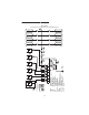
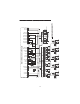
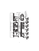
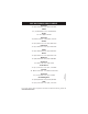
BLOCK DIAGRAM
Typical installation of an irrigation system using the 8060/8050 Controller
Fertilizer and Irrigation
Controller
P11
differential presostate
Filter 1
Water
supply
P12
IP
Filter 2
FC
EF1
EF2
EF3 EF4
Sv1
S1
Sv5
S5
Sv2
S2
Sv6
S6
Sv3
S3
Sv7
S7
Sv4
S4
Sv8
S8
P2
EC1
C
Mixing
pipe
Counter
Fertilizer 1 Fertilizer 2 Fertilizer 3 Fertilizer 4
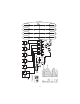
Filter 1
Filter 2
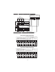
FC
LAT
LAK
LFT
IP
FP
P0, P1, P2
pH1
EC1,EC
EA, EK
EF1...EF4
C
Sv1...Sv8
S1...S8
in
- water supply filter
- second filter (in front of sensor)
- fertilizer counters
- low level tank acid
- low lvel tank alkaline
- low level tank fertilizers
- irrigation pump
- pressure indicators
- pH sensor
- conductivity sensors
- electrovalve for acid (alkaline)
- electrovalve for fertilizer
- flow counter
- sectors electrovalves
- sectors
- fertilization pump
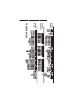
FP
FC FC FC
P0
pH1
P21 P22
EC
in
EA
Acid
LFTLFTLFTLFTLAT
P1
Alk
LAK
Only for
HI 8060
EK