Instruction Manual HI 8050 & HI 8060 Fertigation Controllers These Instruments are in Compliance with the CE Directives Manufacturers since 1978 1
Dear Customer, Thank you for choosing a Hanna Product. Please read this instruction manual carefully before using the controller. This manual will provide you with the necessary information for a correct use of the controller, as well as a precise idea of its versatility. If you need more technical information, do not hesitate to e-mail us at tech@hannainst.com. directives. These instruments are in compliance with TABLE OF CONTENTS THEORY OF FUNCTION ........................................................
Setting Panels ............................................................................. 38 CALIBRATION PROCEDURES ........................................................... 57 Sensor Calibration Procedure ........................................................ 57 ALARMS DESCRIPTION ................................................................... 58 TROUBLESHOOTING GUIDE ........................................................... 60 APPENDIXES .......................................................
THEORY OF FUNCTION Irrigation is one of the most important operation in agriculture. With proper irrigation the quality and quantity of crops can be significantly enhanced. Correct irrigation is not a simple process: the quantity of water must be sufficient for crops, and if not, photosynthesis and overall growth is impeded. However, if the amount of water is more than required, plant growth may become excessive producing a taller, softer and/or damaged product.
GENERAL DESCRIPTION The Fertigation Controller is a micro-processor-based system used in fertilization and irrigation control for greenhouses or open fields with powerful, flexible programming features. The main function of the Fertigation Controller is supplying and controlling the necessary water and fertilizers for crops according to several parameters such as acidity, conductivity and ambient temperature. The user interface is structured in two parts: 1. Consulting (numbered panels indicated by Cxx) 2.
FUNCTIONAL DESCRIPTION In this chapter the main functions of the Fertigation Controller are presented. For a better understanding see the typical installation schemes utilized for irrigation and fertilization presented in the Appendixes, Installation Block Diagram.
The following are setting requirements for each irrigation program: - the working period (between start date (day/month) and end date (day/month)) – use panel S29 (ACTIVE TIMETABLE) - the working time during a day (between start time and end time) – use panel S29 (ACTIVE TIMETABLE) - the cycle work / rest day can be set using panel S30 (WORKDAY) - the working days in a week – use panel S30 (WORKDAY) Working time status for each irrigation program, if selected (irrigation program is in work period of month,
panel C19 (SECTOR ACCUMUL). In addition, this panel displays the valve number assigned with the corresponding sector. Accumulations erase mode can be chosen on panel S65 (ERASE STATISTICS).
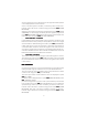
alarm is triggered. For more information on the propotional band please consult the proportional control section. Given a conductivity alarm condition, conductivity control can be maintained if “Ctrl on EC alarm” is selected using panel number S54 (ALARM BEHAVIOR). Statistical values of total conductivity are displayed on panel C20 (TOTAL AVERAGES).
Statistical values of pH are displayed on panel C20 (TOTAL AVERAGES). For each irrigation program the pH average is available on panel C21 (PROGRAM AVERAGES) and for each individual sector the pH average is available on panel C22 (SECTOR AVERAGES). All pH averages can be deleted manually or at specified time of day using panel S65 (ERASE STATISTICS) PROPORTIONAL CONTROL EC and pH control is performed using a proportional controller.
circulated. The amount of additive solution added is relative to the opening of the valve, which is directly proportional to the magnitude of difference between the “water pool” pH and the set point. Set point (reference value) is the desired value of the measurement.
100% 80% 0 100% 80% P Control Low Alarm Area Proportional Band Control cycle percentage Dead Band Dead Band No Valve Control Setpoint High Alarm Area Proportional Band P Control Max pH Max EC Valve Opening pH, EC Valve Opening
AGIT ATOR CONTROL AGITA For HI8060: The agitator output is active in the irrigation phase of a program if the fertilizer control is enabled. This output also commands the fertilization pumps. For HI8050: During the irrigation program, the agitators can be stopped (if working time is zero), work continuously (if pause time is zero) or intermittently (if working time and pause is different than zero) and can start during preirrigation, before the fertilizer tanks are used.
ALARMS Fertigation controller has the capability to supervise and generate an alarm for the following conditions: - Conductivity sensor out of range. Reference, minimal and maximal offset and time-out for conductivity alarm are set using panel S38 (EC CONTROL). The current values of conductivity sensors are displayed on panel C06 (EC STATE).. − pH sensor out of range. Reference, minimum and maximum offset and time-out for pH alarm are set using panel S36 (PH CONTROL).
- Values of sensors. - Sectors irrigated by a program. - Alarms; The records of log can be searched by date. To start a search set the desired date in panel C24 (VIEW LOG DATE). Logging records are displayed on panel C26 (LOG). The average value of sensors and accumulation of volumes are available through panes C17 (TOTAL ACCUMUL) to C22 (SECTOR AVERAGES).
USER INTERFACE The user interface of the Fertigation Controller consists of a 4 x 20 character LCD and a 23 key keyboard (see depiction below). KEYBOARD STRUCTURE Fig. 1.1: Keyboard layout. OPERA TING MODES OPERATING The Fertigation controller operates primarily in two major modes: Consulting Mode and Setting Mode. User interface panels (screens) are broken down into two categories: 1. CONSULTING PANELS 2. SETTING PANELS Both modes of operation a readily available to the user. 1.
− ESC key can be used as a shortcut key to access the C04 (PROGRAM STATE) panel from any currently viewed panel. − HOME key can be used as a shortcut key to access the C01 (GENERAL INFO) panel from any currently viewed panel. − END key can be used as a shortcut key to access the S48 (PROG MAN STOP) panel from any currently viewed panel. − TAB key can be used to switch the focus between the panel number object and the panels index parameter if the current panel is indexed.
ENTER key is pressed and data confirmed, the controller reverts to consulting mode. The SET key must be pressed to re-enter setting mode. − ESC key cancels new data entered in the currently focused data object and exits the setting mode. The change of data is not saved in the current object and the previous setting is maintained. NO TE NOTE TE: Data that has been changed in an editable data object is saved once focus has been removed from that object by pressing the ARROW KEYS or TAB AB.
PANEL LIST PANEL TABLE BY NUMBER CONSULTING PANELS SETTING PANELS 01 GENERAL INFORMATION 28 SET DATE & TIME 02 VOLUME STATE 29 ACTIVE TIME TABLE 03 SENSORS STATE 30 WORKDAY 04 PROGRAM STATE 31 SET PRIORITY 05 pH STATE 32 START CONDITIONS 06 EC STATE 33 SET START TIME 07 WORK TIME CONDITIONS 34 PROGRAM REPEATS 08 PRIORITY & CONFLICTS 35 PRE / POST IRRIGATION 09 IRRIGATION STATE 36 pH CONTROL 10 MANUAL CORRECTION FACTOR 37 FERTILIZER CONTROL MODE 11 TOTAL CORRECTION 38 EC CONTROL 12 EC
PANEL TABLE BY NUMBER CONSULTING PANELS SETTING PANELS 25 ANOMALIES 52 VOLUME DOSING ALARMS 26 LOG 53 STOP ON VOLUME ALARMS 27 GOOD LABORATORY PRACTICE 54 ALARM BEHAVIOR 55 IRRIGATION CONTROL MODE 56 SET FLOW PARAMETERS 57 COUNTER SETTINGS 58 PUMPS SELECTION 59 MOTORIZED VALVES 60 SET PROP CTRL 61 SET TIMINGS 62 ENABLE CONTROL 63 LOGIGNG SENSORS SET 64 SET PASSWORD 65 ERASE STATISTICS 66 ERASE SETTINGS 67 CALIBRATE SENSORS 68 CONTROLLER IDENTIFICATION 20
PANEL TABLE BY FUNCTION PANEL FUNCTION GENERAL (CONTROLLER) CONSULTING PROGRAM CONSULTING STATISTICS CONSULTING PANEL NUMBER PANEL NAME 01 GENERAL INFORMATION 03 SENSORS STATE 27 GOOD LABORATORY PRACTICE 02 VOLUME STATE 04 PROGRAM STATE 05 pH STATE 06 EC STATE 07 WORK TIME CONDITIONS 08 PRIORITY AND CONFLICTS 09 IRRIGATION STATE 10 MANUAL CORRECTION FACTOR 11 TOTAL CORRECTION 12 EC CORRECTIONS 13 SENSORS STATE 14 FERTILIZER STATE 15 AGITATOR STATE 16 PROGRAM LAST START
PANEL TABLE BY FUNCTION PANEL FUNCTION GENERAL (CONTROLLER) SETTINGS PROGRAM SETTINGS PANEL NUMBER PANEL NAME 25 ANOMALIES 26 LOG 28 SET DATE & TIME 37 FERTILIZER CONTROL MODE 46 FILTERS CONTROL 51 pH CONTROL OPTIONS 52 VOLUME DOSING ALARMS 53 STOP ON VOLUME ALARMS 54 ALARM BEHAVIOR 56 SET FLOW PARAMETERS 57 COUNTER SETTINGS 59 MOTORIZED VALVES 60 SET PPOP CTRL 61 SET TIMINGS 62 ENABLE CONTROL 63 LOGGING SENSORS SET 64 SET PASSWORD 67 CALIBRATE SENSORS 68 CONTROLLER
PANEL TABLE BY FUNCTION PANEL FUNCTION MANUAL FUNCTIONS PANEL NUMBER PANEL NAME 35 PRE / POST IRRIGATION 36 pH CONTROL 38 EC CONTROL 39 SET FERTILIZERS 40 EC DIFFERENTIAL CONTROL CONFIGURATION 41 RATIOMETRIC FERTILIZER CONTROL 42 VOLUME FERTILIZER CONTROL 43 SET SECTORS 44 IRRIGATION CORRECTION 45 SET AGITATORS 55 IRRIGATION CONTROL MODE 58 PUMPS SELECTION 47 PROGRAM MANUAL START 48 PROGRAM MANUAL STOP 49 CONTROLLER STATE 50 OUTLETS MANUAL CONTROL 65 ERASE STATISTICS 66
PANEL DESCRIPTIONS Below are described all the panels in the controllers. The panels are divided in three sections: Initialization panels, consulting panels and setting panels. The data fields within each panel are described from left to right unless otherwise specified. ANELS INITIALIZATION PANELS INITIALIZA TION P INITIALIZATION PANEL HANNA INSTRUMENTS HI8050 V00.
INPUT PASSWORD PANEL Enter password: **** This panel is displayed during the password authentication sequence. If this AR T panel will be dissequence fails the user will be logged off and the ST STAR ART played. If the password is correct panel C01 (GENERAL INFO) is displayed. The default password is 0000 0000. See section Setting Password for instructions on setting this feature.
− Program Number - The active program is displayed. If no program is active this field is not visible. − pH sensor reading - The reading of pH sensor. − Sector Numbers - All sectors assigned to the active program are displayed (cyclically) and only when an active program is running. If no program is active no number is visible. − EC sensor reading - The reading of EC sensor. − System clock. If an alarm condition is present the time indication will also flash “ALARM” to alert the user.
This panel contains the following information: − Active program number - displays the number of the executing program. If no program is running no number is displayed. − pH sensor reading − Temperature sensor reading − EC sensor reading − System clock. PROGRAM STATE – C04 Prog 08 Started Repeat PROGRAM Active by Time Cond 02/05 13:15 STATE C04 The purpose of this panel is to allow the user to inspect the status and settings of a particular program. The program number indexes this panel.
− System clock REMINDER: In CONSULTING MODE the ESC key can be used as a shortcut key to access this panel from any panel. PH STATE – C05 Prog 08 Ref=06.4pH pHout:06.4pH PH STATE 13:15 C05 The purpose of this panel is to allow the user to inspect the current pH reference point for a specific program and the real time pH sensor readings. The program number indexes this panel. This panel contains the following information: − Program Number – The current selected program.
WORK TIME COND – C07 Prog WORK 08 Time Y Day Y Period Y TIME COND 13:15 C07 The program number indexes this panel. This panel contains the following information: − Program Number - Panel index (used to view settings for all programs).
IRRIG STATE – C09 Prog 08 IRRIG Set 01:15:20+005:55 Done 00:45:10 13:15 IRRIG STATE C09 This panel displays the current irrigation state of the indexed program. Time or volume can control irrigation and the above panel displays the set value and the amount of irrigation currently completed. The mode of irrigation (time or volume) can be selected using panel S55 (IRRIG CTRL MODE). The program number indexes this panel.
This panel displays how much the programmed irrigation parameters are modified due to both manual and temperature corrections. The program number indexes this panel. This panel contains the following information: − Program Number - Panel index (used to view settings for all programs). − Irrigation extension percentage - Displays the overall extension percentage for a selected program. − Irrigation extension value - Displays (time or volume) the total extension value of irrigation for the selected program.
valve number assigned to that sector. This parameter indexes the sectors for this panel. − Set - Displays the amount of irrigation water set in time or volume for the selected sector/valve of the indicated program. − Irrigation correction value (number directly following Set value) - Displays correction value in time or volume for the selected sector/valve of the indicated program. − Done - Displays the current point of irrigation in time or volume for the selected sector/valve of the indicated program.
This panel displays the state of the agitator for the current selected program. The agitators can be activated before dosing of a fertilizer, during dosing, or intermittently throughout the program. The program number indexes this panel. This panel contains the following information: − Program Number - Panel index (used to view settings for all programs). − Work – the set working time for the agitator. − Pause – the set pause time for the agitator. − System clock.
(all programs) from the reset time. All Fertigation Controller’s statistics including accumulations can be erased (manually, daily at specified hour, on overflow ) within panel S 65 (ERASE STATISTICS). This panel contains the following information: - From - Time stamp indicating the beginning of the overall irrigation process. - Accumulation - Total accumulation in time or volume - Accumulation label - Accumulation label can be changed by using the up and down arrows.
This panel provides a total (in time or volume) for each of the irrigation sectors. The valve number indexes this panel. This panel contains the following information: − From - Time stamp indicating the start of recording (statistics) − Accumulation - Total accumulation in time or volume for the indexed valve and type of accumulation selected on panel C17 (TOTAL ACCUMUL). − Sect - The sector number (label) / valve number (index for this panel). − System clock. TOTAL AVERAGES – C20 From: 09-26 13:37:12 05.
SECTOR AVERAGES – C22 From: 09-26 13:37:12 05.3pH Sect 01/01 02.1mS +21C 13:15 SECTOR AVERAGES C22 This panel provides an average pH, EC and temperature reading for each of the irrigation sectors. The valve number indexes this panel. This panel contains the following information: − From - Time stamp indicating the start of recording (statistics) − pH - The average pH reading for the indexed valve. − Sect - The sector number (label) / valve number (index for this panel).
VIEW LOG DATE – C24 Log VIEW consulting 26-12 LOG DATE date: 15:05 C24 This panel allows the user to view log data from a specific date. The SET key is used to enter the date of choice thus entering the setting mode. After entering the panel and pressing the SET key, the cursor (focus) is shifted from the panel number to the first place of the day indicator. The key pad and arrow keys can be used to enter the selected date followed by the ENTER key.
This panel is meant to display the records from log after a search has been started in panel C24 (VIEW LOG DATE). The UP and DOWN arrow keys are available to move between log records in a “select previous/next” manner. This panel displays the following information: − Log record - Log record description. − Time stamp - Time stamp of logged occurrence. − System clock. − Log record number GLP – C27 pH pH Slope :59.
once the numeric date is entered and confirmed. − Time - Hour / Minute / Seconds format. The time is automatically updated once the numeric time is entered. − System clock. ACTIVE TIMETABLE – S29 BetWeen Prog 07 Date: 01-04 31-10 Time: 07:00 23:00 ACTIVE TIMETABLE S29 This program allows the user to set the scheduled limits for the indexed program. The program number indexes this panel.
− Weekday - Weekday labels − Workday - Use yes or no indication (on keypad) below each weekday label to indicate specific workdays for the indexed program. SET PRIORITY – S31 Priority Sector/Group SET PRIORITY Prog 04 08 07 S31 This panel allows the setting of priority level for each program. Programs can share the same priority level. When a conflict occurs between two programs with the same priority, the program with the earliest starting time will execute first. The program number indexes this panel.
SET START TIME – S33 Prog 07 07:00 09:20 10:30 12:00 14:00 16:00 SET START TIME S33 If time is selected as the starting trigger for an indexed program, up to six different starting times within the daily schedule limits (see panel S29 (ACTIVE TIMETABLE)) can be selected. The program number indexes this panel. This panel displays and allows the setting of the following parameters: − Program Number - Panel index (used to view settings for all programs).
− Program Number - Panel index (used to view settings for all programs). − PreIrrig - The selectable amount of pre-irrigation water in time or volume. − PostIrrig - The selectable amount of post-irrigation water in time or volume. PH CONTROL – S36 pHRef=07.3pH Prog 01 pHBnd: D=00.5 P=01.0 TimeOut:03min PH CONTROL S36 Typically an acid is added to reduce the pH to a desired level. The Fertigation Controller can control 1 acid tank.
EC CONTROL – S38 ECRef=07.3mS Prog 07 ECBnd: D=00.5 P=01.0 TimeOut:03min EC CONTROL S38 The EC settings are programmed using this panel. EC control determines the overall amount of fertilizer added to the irrigation water to maintain the desired conductivity value. The Fertigation Controller controls up to 4 fertilizer tanks relative to the EC settings established using this panel. The program number indexes this panel.
NO TE NOTE TE:: These settings are for the EC fertilizer control mode only. EC DIFF CTRL CFG – S40 Prog 01 EC differential: Y Ideal ECIn : 00.5mS EC DIFF CTRL CFG S40 This panel allows the setting of differential EC control. Differential control is a EC control mode where the EC reference is incremented with the value that the EC of incoming water exceeds the ideal EC of the incoming water.
− Conc – specify the active substance concentration of the fertilizer solution. It is used only in weight mode. FERT VOL CTRL – S42 Tank:Fert1 Prog:01 Fert: 00300L Water:0500000L FERT VOLUME CTRL S42 This panel controls the dosing of fertilizer in the volume mode. This fertilizer dosing mode works only if the controller is in volume mode. For this mode the volume of fertilizer solution is specified together with the quantity of water for which is needed. The valve number indexes this panel.
− Total - Total number of valves assigned to the indicated program. − Value - The selectable irrigation (time or volume) value for the indexed valve. IRRIGATION CORR – S44 Manual +050% Prog 07 Temp extension:+010% TLow:+20C THigh:+40C IRRIGATION CORR S44 This panel allows the setting of corrections (adjustments) to the irrigations and fertilization process. The program number indexes this panel.
− Link - The selectable program (number) after which the filter-cleaning program is activated. − Filter Number - Panel index. Two filter selectable. − Clean on alarm - The filter-cleaning program can be set to be activated by an alarm condition alone or in addition to being linked to a specific program. Enter Y (yes) or N (no). − Clean time - Selectable work duration for the indexed filter cleaning program.
MANUAL STOP – S48 Active Stop PROG program: program: MAN STOP 03 -- ? S48 Each program can be manually stopped using this panel. This panel displays and allows the setting of the following parameters: − Active program - The currently active program. − Stop program - The program selected for deactivation. User selectable. CONTROLLER STATE – S49 STOP WORK INIT CONTROLLER WORK STATE S49 This panel allows manual manipulation of the controller state.
PH CTRL OPTIONS – S51 Ctrl in Pre/Post Use acid in pHCtrl PH CTRL OPTIONS Y Y S51 This panel allows selection of pH control options. Control in “pre” and “post” irrigation states as well as acid or base selection is selectable. This panel displays and allows the setting of the following parameters: re / PPost ost - Enter Y (yes) then ENTER to control pH prior and after − Ctrl in PPre irrigation.
ALARM BEHAVIOR – S54 Ctrl Irrig Ctrl ALARM on pH alarm: Y on pH alarm: Y on EC alarm: Y BEHAVIOR S54 This panel allows the selection of specific Ec/pH alarm behavior. Once entering the set mode, one of the 3 choices can be selected using the arrow keys. Y (yes) can be entered next to the selected option. Y (yes) and N (no) keys are used to select the option of continuing or stopping control or irrigation during a pH or EC alarm condition.
This panel allows the setting of the flow parameters. The sector number indexes this panel. This panel displays and allows the setting of the following parameters: − Flow - The selectable volume percent for the indexed sector. It is used to calculate the water used on each sector based on the total amount of water measured by the main counter. − Sect - The panel index. The sector number (label). − Max. time – the time-out after which the main counter fail alarm is triggered.
diameter of the pipe from the main pipe to the sector’s valve, or the minimum section that appears on that pipe. NOTE: if the pipes are clogged up the correct computing of the quantity of water might be impeded! COUNTER SETTINGS – S57 Fert1=1000mL/pulse COUNTER SETTING S57 This panel allows the setting of the counter factor for the fertilizers. The Fert field is index of this panel. This panel displays and allows the setting of the counter factor.
and fertilizers. This panel displays and allows the setting of the following parameters: − Max Lit Time – the time needed for a motorized valve to open completely from a full close position. It has to be the same for all motorized valves. − Close pH If Idle – if set ‘Y’ the control valves for pH will be closed if the control of pH is idle for a period of time. − Close Fert If Idle – if set ‘Y’ the control valves for fertilizer will be closed if the control of fertilizers is idle for a period of time.
the control cycle of the proportional control is used. WARNING! It is strongly recommended that modification to these settings to be made only by specialized personnel. ENABLE CONTROL – S62 EC/Fertilizer CTRL:Y pH CTRL: Y Ignore All Alarms: Y ENABLE CONTROL C62 This panel allows the manual stop of the fertilization and pH control. It also allows a setting for operation of the controller even when critical alarms are active.
displays and allows the setting of the following parameters: − Disable password - Choosing Y for the “Disable password” option will allow free access to the Fertigation Controller after every start-up sequence, while choosing N will enable start-up after which password authorization will be required to view display panels. − New password - New password input. NOTE: The function of the Fertigation Controller is not affected due to a failed or successful password authorization process during log on.
CALIBRATE SENSORS – S67 Channel: 01 Now: 02.3 Ref: 02.5 Status: First stage CALIBRATE SENSOR S67 The sensor calibration procedure consists of two stages. Each stage is initiated by pressing SET key. See section SENSOR CALIBRATION PROCEDURE for more information. Both stages are required to complete the calibration procedure. The channel number indexes this panel. This panel displays and allows the setting of the following parameters: − Channel number - Panel index.
CALIBRA TION PROCEDURES CALIBRATION IMPORTANT WARNING !!! The pH and EC sensors of Fertigation Controller must be connected ONLY via HI 98143-22 series transmitters which are function using current injection principle (4-20mA). The sensors cannot be directly connected to the controller.
the temperature sensor in the water and ice mixture along with the reference thermometer. Allow the temperature readings to stabilise for both controller and reference thermometer. In the calibration panel select chanel 4 (temperature sensor) and press the SET key. Introduce the temperature in the reference field according to the reference thermometer.Press the ENTER keyto confirm. For this step the reference value should be 0. For the second stage replace the ice-water mixture with hot water (about 50°C).
valve will close and that fertilizer tank will be excluded from use during fertilization control of the irrigation process. 5. Low level acid This alarm is triggered if the level of the acid (or alkaline) tank has reached a minimum value. Once this alarm is triggered, the assigned valve will close and that tank will be excluded from use during pH control of the irrigation process. 6. No water supply This alarm is triggered due to an incoming water supply failure event.
irrigation water. NOTE: - the overdose and underdose thresholds are not the same (set from panel 30 VOLUME DOSING ALARMS). Both alarms are triggered if the overdose/underdose alarm trigger condition is TRUE for more than 3 dosing cycles! 10. FERTILIZER WASTE ALARM: This alarm is triggered if the counter of an fertilizer is changing state (transition), when this should not happen, it means that the fertilizer is flowing when it should not.
the settings are correct. Also you should check the pH tank and supply lines for proper level and function. Check the pH level of the incoming water to determine if a change has occurred that may not be correctable by the type and amount of acid (or base) being used. If the problem persists after checking the process pH and acid or base supply, check panel S60 (SET PID PARAMETERS) to be sure that the control algorithms are correct.
APPENDIXES PANEL LIST WORK Prog 08 Sect 07 GENERAL Anomalies 00 06.4pH 02.1mS 13:15 INFO C01 Irr:0114320L Prog:01 F1:00050L F2:00500L F3:00370L F4:00000L VOLUME STATE C02 Active Program: 04 06.3pH +22C 02.1mS 13:15 SENSORS STATE C03 Prog 08 Started Repeat PROGRAM Prog Active by Time Cond 02/05 13:15 STATE C04 08 Ref=06.4pH pHout:06.4pH PH STATE 13:15 C05 Prog 08 Ref=02.1mS ECin :01.1mS Count:02.
Prog 08 IRRIG Set 01:15:20+005:55 Done 00:45:10 13:15 IRRIG STATE C09 Prog MAN 08 +015% +00:15:55 CORRECTION 13:15 C10 Prog 08 +035% +02:00:13 13:15 TOTAL CORRECTION C11 Prog 08 Ref=05.6mS TCorr:-00.3mS Input:+01.
From: 09-26 13:37:12 0007654L Prog 01 ActivatIons 03 13:15 PROGRAM ACCUMUL C18 From: 09-26 13:37:12 0123456L Sect 01/01 13:15 SECTOR ACCUMUL C19 From: 09-26 13:37:12 05.3pH 02.1mS +21C 13:15 TOTAL AVERAGES C20 From: 09-26 13:37:12 05.3pH Prog 01 02.1mS +21C 13:15 PROGRAM AVERAGES C21 From: 09-26 13:37:12 05.3pH Sect 01/01 02.
pH pH Slope :59.
pHRef=07.3pH Prog 01 -00.5pH +00.5pH TimeOut:03min PH CONTROL S36 EC Ctrl: Y Prog:01 Ratiometric Ctrl:N Vol Ctrl: N FERT CTRL MODE S37 ECRef=07.3mS Prog 07 -00.5 mS +00.5mS TimeOut:03min EC CONTROL S38 Prog 07 Fer1=020% Fer2=055% Fer3=060% Fer4=040% SET FERTILIZERS S39 Prog 01 EC differential: Y Ideal ECIn : 00.
Pre 00:33 Prog 08 Work 00:10 Pause 00:05 SET AGITATORS S45 Link 05 Filter 01 Clean on alarm: Y Clean time: 01:01:02 FILTERS CTRL S46 Active Start PROG MAN Active Stop PROG program: program: START 03 -- program: program: MAN STOP STOP WORK INIT CONTROLLER ? S47 03 -- ? S48 WORK STATE S49 Number: 27 Opened: Y Value: OUTLET MAN CTRL S50 Ctrl in Pre/Post Use acid in pHCtrl PH CTRL OPTIONS Overdose: Underdose: VOL DOSE S51 +10% -20% ALARM Overdose: N Underdose: N Tank empty:Y STOP ON VOL AL
Ctrl Irrig Ctrl ALARM on pH alarm: Y on pH alarm: Y on EC alarm: Y BEHAVIOR S54 Program 01 Volume control: Time control: IRRIG CTRL MODE N Y S55 Flow=100% Sect 01 Max. time =00:30H:m L/impulse=0010 SET FLOW PARAMS S56 Fert1=1000mL/pulse COUNTER Pump1 Pump2 Pump3 PUMPS SETTING S57 En:Y Prog 07 En:Y En:Y SELECTION S58 Max Lit Time: S Close pH If Idle :Y Close Fert If Idle:Y MOTORIZED VALVES S59 PHk =01.0 ECk =01.3 PHTi=10.0 ECTi=10.0 PHTd=00.5 ECTd=00.
EC Resolution:00.5mS pH Resolution:00.5pH Temp Resolution: 01C LOG SENSORS: S63 Disable password: N New password: ---SET PASSWORD S64 Erase all: On overflow: Y Daily at hour: 00:01 ERASE STATISTICS S65 Erase Erase program: -all programs ERASE SETTINGS - S66 Channel: 01 Now: 02.3 Ref: 02.
SETTING MODE: - UP, DOWN arrow keys can be used for navigating between all editable parameters - Left, Right arrow keys can be used to navigate inside the currently focused parameter - TAB key can be used to move only in forward direction between editable parameters - ENTER key can be used to validate all data exchanges in the current TING MODE panel and enables switching back to CONSUL CONSULTING MODE. - ESC key can be used to cancel the last data exchange for the last TING MODE CONSULTING MODE.
Outlet Number HI8050 HI8060 Only HI8050 27 28 29 30 31 32 33 Sector Valve 1 34 Sector Valve 2 35 Sector Valve 3 36 Sector Valve 4 37 Sector Valve 5 38 Sector Valve 6 39 Sector Valve 7 40 Sector Valve 8 41 Sector Valve 9 42 Sector Valve 10 43 Sector Valve 11 44 Sector Valve 12 45 Sector Valve 13 46 Sector Valve 14 47 Sector Valve 15 48 Sector Valve 16 49 Sector Valve 17 50 Sector Valve 18 51 Sector Valve 19 52 Sector Valve 20 53 Sector Valve 21 54 Sector Valve 22
Alk Filter 1 Filter 2 FC LAT LAK LFT IP FP P0, P1, P2 pH1 EC1,ECin EA, EK EF1...EF4 C Sv1...Sv8 S1...
Filter 1 Filter 2 LAT LAK LMT LFT HLC P11, P12, P21, P22 P0, P1, P2 IP pH1 EC1, ECin EA EK EF1...EF4 C Sv1...Sv8 S1...S8 FC1..
+Vs +Vs - Vs - Vs (12V) (12V) (12V) (12V) UNUSED UNUSED DIFF PRESS 2 DIFF PRESS 1 TEMP SENSOR EC IN SENSOR EC SENSOR pH SENSOR COM IN COM IN EXT SENSE TEMPORARY BREAK EXT TANK ALK/ACID LEVEL FERT 4 LEVEL FERT 3 LEVEL FERT 2 LEVEL FERT 1 LEVEL WATER 3 INCOMING WATER 2 INCOMING WATER 1 INCOMING FERT 4 COUNTER FERT 3 COUNTER FERT 2 COUNTER FERT 1 COUNTER IRRIG COUNTER POWER BOARD EXTENSION BOARD MAIN BOARD FRONT (HI8050) ELECTRICAL CONNECTION DIAGRAM IN 24 Vac IN 24 Vac 4A VALVE 24 VALVE 23 VALVE 22
(12V) (12V) (12V) (12V) UNUSED UNUSED DIFF PRESS 2 DIFF PRESS 1 TEMP SENSOR EC IN SENSOR EC SENSOR pH SENSOR COM IN COM IN EXT SENSE TEMPORARY BREAK ALK LEVEL ACID LEVEL FERT 4 LEVEL FERT 3 LEVEL FERT 2 LEVEL FERT 1 LEVEL EXT TANK WATER 2 INCOMING WATER 1 INCOMING FERT 4 COUNTER FERT 3 COUNTER FERT 2 COUNTER FERT 1 COUNTER IRRIG COUNTER POWER BOARD EXTENSION BOARD MAIN BOARD FRONT (HI8060) +Vs +Vs - Vs - Vs IN 24 Vac IN 24 Vac 4A VALVE 24 VALVE 23 VALVE 22 VALVE 21 VALVE 20 VALVE 19 VALVE 18 VALVE
PE PUMP 3 PUMP 1 PUMP 2 COM OUT AL IN 220VAC IN 220VAC M pH CLOSE FERT 1 PUMP M FERT 2 PUMP FILTER 1 M pH OPEN FERT 3 LOW LEVEL SIGNAL FILTER 2 ALK/ACID PUMP FERT PUMP FERT 2 LOW LEVEL SIGNAL AGITATORS FERT 1 LOW LEVEL SIGNAL FERT 3 CLOSE FERT 4 LOW LEVEL SIGNAL AGIT 4 FERT 3 PUMP M R S T AGIT 3 FERT 4 OPEN AGIT 2 FERT 3 OPEN FERT 4 PUMP M R S T FILTER-CLOSE NOTE: THE MOTORS FOR pH AND FERTILIZER PUMPS MUST HAVE PROTECTION RELAYS COMMANDED BY THE LOW LEVEL SENSOR OF THE
PE ALK CLOSE PUMP 2 COM OUT AL IN 220VAC IN 220VAC FERT 1 PUMP ACID OPEN pH 2 PUMP FILTER 1 pH 1 PUMP ACID CLOSE M FILTER 2 FERT 2 LOW LEVEL SIGNAL FERT 2 PUMP M FERT PUMP M PUMP 1 FERT 1 LOW LEVEL SIGNAL FERT 3 CLOSE FERT 3 PUMP M R S T AGIT 4 FERT 3 LOW LEVEL SIGNAL AGIT 3 FERT 4 OPEN R S T FERT 3 OPEN AGIT 2 FERT 4 CLOSE FERT 4 LOW LEVEL SIGNAL FILTER-CLOSE IF FERTILIZER LOW LEVEL SIGNAL, IS ACTIVE, DISCONNECT FERTILIZER X PUMP (TO PREVENT DAMAGE).
DIGITAL INPUT CONNECTIONS HI8060 78 COM IN - COM IN S 2 COM IN EC COM IN 0 EXT SENSE S 1 EXT SENSE pH TEMP BREAK 0 - TEMP BREAK S h S 2 EXT TANK NTC EC ALK LEVEL HI198143-22 0 ALK/ACID LEVEL CONDUCTIVITY SENSOR S 1 ACID LEVEL pH FERT 3 LEVEL FERT 4 LEVEL 6 0 FERT 2 LEVEL 5 S h FERT 3 LEVEL FERT 4 LEVEL EC sensor 6 FERT 1 LEVEL NTC FERT 2 LEVEL 4 5 WATER 3 INCOMING 3 4 - EXT TANK SHIELD FERT 1 LEVEL SHIELD WATER 2 INCOMING EC sensor WATER 1 INCOMING °C + WATER
WARRANTY All Hanna controllers are warranted for two years against defects in workmanship and materials when used for their intended purpose and maintained according to instructions. Damages due to accident, misuse, tampering or lack of prescribed maintenance are not covered. This warranty is limited to free of charge or replacement of the meter only, if any malfunctioning is due to manufacturing defects. If service is required, contact the dealer from whom you purchased the instrument.
SALES AND TECHNICAL SERVICE CONTACTS Australia: Tel. (03) 9769.0666 • Fax (03) 9769.0699 China: Tel. (10) 88570068 • Fax (10) 88570060 Egypt: Tel. & Fax (02) 2758.683 Germany: Tel. (07851) 9129-0 • Fax (07851) 9129-99 Greece: Tel. (210) 823.5192 • Fax (210) 884.0210 Indonesia: Tel. (21) 4584.2941 • Fax (21) 4584.2942 Japan: Tel. (03) 3258.9565 • Fax (03) 3258.9567 Korea: Tel. (02) 2278.5147 • Fax (02) 2264.1729 Malaysia: Tel. (603) 5638.9940 • Fax (603) 5638.9829 Singapore: Tel. 6296.