
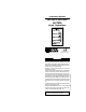
User Guide
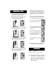

• With HI 7873, connect terminals #10 and #11 to an
alarm for monitoring Over Flow condition.
• Remove the cover of HI 7874 (bar holder) and connect
a 2-wire cable from #8 to positive (+) and #9 to
negative (–) terminals of the holder.
The common terminal (#4) and #3 can also be
connected to a device to indicate a “full tank” state.
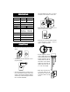
• Screw the longest bar to the hole
marked as COMM. This bar will be
used as the reference electrode. Screw
the other measuring bars into the
remaining sockets in any order. The
bars should be cut to the required
lengths for low, high and over. The
reference (COM) and the low bar
(1
st
) can be the same length.
• With HI 7871, connect only 3 bars
to the holder: reference, low and
high. With HI 7873, connect 4 bars
to the holder: reference, low, high
and over.
SPECIFICATIONSSPECIFICATIONS
SPECIFICATIONSSPECIFICATIONS
SPECIFICATIONS
HI 7871 HI 7873
Level Adjustment High, Low High, Low, Over
Level Indication High, Low High, Low, Over
Transmission 300 m (990') max
Socket/Connector 11-pin connector
Sensing Bars* 34
Transmitter* HI 7874
Output Contact One, 2A/220V Two, 2A/220V
relay for up to relays for up to
1,000,000 closures 1,000,000 closures
Power Supply 110/115V or 220/240V –50/60 Hz
Environment 0 to 50°C (32 to 122°F)
Max. 85% RH non-condensing
Dimensions 79 x 49 x 95 mm (3.1 x 1.9 x 3.7")
Weight 130 g (4.6 oz.)
CONNECTIONSCONNECTIONS
CONNECTIONSCONNECTIONS
CONNECTIONS
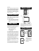
• Remove the 11-pin connector from the rear of the level
controller.
• Connect a 2-wire power cable to terminals #2 and #7
(no ground connection).
• Connect the output terminals #4 (common) and #5
(low) to a relay switch (max 2A/220V) to start and stop
a pump or to open and close an electrovalve. These two
contacts act only as a switch and the pump or electrovalve
have to be powered independently.
* Not included with HI 7871/7873.