HI 700 / HI 710 Series Process, Panel-mounted, Microprocessor-based, Conductivity and TDS Controllers Instruction Manual
Dear Customer, Thank you for choosing a Hanna Product. This instruction manual has been written for the following products: HI 700221 EC controller with dual setpoint, ON/OFF and PID control, analog output. HI 700222 EC controller with dual setpoint, ON/OFF and PID control, RS485 port. HI 710221 HI 710222 EC and TDS controller with dual setpoint, ON/OFF and PID control, analog output. EC and TDS controller with dual setpoint, ON/OFF and PID control, RS485 port.
TABLE OF CONTENTS PRELIMINARY EXAMINATION . . . . . . . . . . . . . . . . . . 4 GENERAL DESCRIPTION . . . . . . . . . . . . . . . . . . . . . 4 FUNCTIONAL DESCRIPTION . . . . . . . . . . . . . . . . . . 6 MECHANICAL DIMENSIONS . . . . . . . . . . . . . . . . . . 7 SPECIFICATIONS . . . . . . . . . . . . . . . . . . . . . . . . . . . 8 INSTALLATION . . . . . . . . . . . . . . . . . . . . . . . . . . . . 9 SETUP MODE . . . . . . . . . . . . . . . . . . . . . . . . . . . . 12 CONTROL MODE . . . . . . . . . . .
PRELIMINARY EXAMINATION Remove the instrument from the packing material and examine it carefully to make sure that no damage has occurred during shipping. If there is any noticeable damage, notify your Dealer or the nearest Hanna Customer Service Center immediately. Note Save all packing materials until you are sure that the instrument functions correctly. Any damaged or defective items must be returned in their original packing materials together with the supplied accessories.
• Four different EC working ranges (0 to 199.9µS; 0 to 1999µS; 0 to 19.99mS; 0 to 199.9mS). • Four different TDS working ranges (0 to 100.0ppm; 0 to 1000ppm; 0 to 10.00ppm; 0 to 100.0ppm) for HI 710 models. • Possibility to switch to TDS measurements with conversion factor from 0.00 to 1.00 (HI 710 models only). • Temperature compensation of the HANNA standard solutions. • Temperature compensation of the EC and TDS reading with temperature coefficient ß selectable from 0 to 10%/°C.
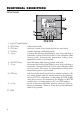
FUNCTIONAL DESCRIPTION FRONT PANEL 1. 2. 3. 4. 5. 6. 7. 8. 9. 10. 6 Liquid Crystal Display SETUP key enters setup mode CFM key confirms current choice (and skips to the next item) CAL key initiates and exits calibration mode key increases the blinking digit/letter by one when selecting a parameter. Advances forward while in last calibration data viewing mode.
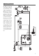
REAR PANEL 1. 2. 3. 4. 5. 6. 7. 8. 9. 10. 11. 12. 6-pin RS485 terminal (HI 700222 and HI 710222 only) Analog Output (HI 700221 and HI 710221 only) Power Supply Alarm Terminal Contact 2 - Second Dosing Terminal Timer Hold Contact 1 - First Dosing Terminal Pt 100 Temperature Sensor connector EC/TDS probe connector Power supply output for external transmitter 4-20 mA input from external transmitter Unplug the meter before any electrical connection.
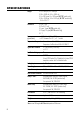
SPECIFICATIONS Ranges 0.0 to 199.9 µS, 0 to 1999 µS 0.00 to 19.99 mS, 0.0 to 199.9 mS 0.0 to 100.0 ppm, 0 to 1000 ppm (HI 710* models only) 0.00 to 10.00 ppt, 0.0 to 100.0 ppt (HI 710* models only) -10.0 to 100.0 °C Resolution 0.1 µS, 1 µS 0.01 mS, 0.1 mS 0.1 ppm, 1 ppm (HI 710 models only) 0.01 ppm, 0.1 ppm (HI 710 models only) 0.1 °C Accuracy ±0.5 % full scale (EC and TDS) ±0.
INSTALLATION HI 700 and HI 710 series offer a multitude of possibilities, from single and dual setpoints to ON/OFF or PID dosage, isolated outputs with user-selectable zoom, bi-directional RS485, recorder outputs in mAmps and Volts. Use the 3-wire Pt 100 temperature sensor to compensate for the cable resistance and have a precise automatic temperature compensation of the measurements in long distance applications. See the diagram for a recommended installation.
• Power Supply: Connect a 3-wire power cable to the terminal strip, while paying attention to the correct live (L), earth (PE) and neutral (N) terminal connections. Power: 115VAC -100 mA / 230VAC - 50 mA. Live Contact: fused inside 200mA. PE leakage current 1 mA; this contact must be connected to ground. • Conductivity input: the default input is from conductivity probe. Connect the EC probe to the terminals #10 on page 7.
If the Pt 100 has more than 2 wires, connect the two wires of one end to pins 7 and 8 (pin 7 is an auxiliary input to compensate for the cable resistance) and one wire from the other end to pin 6. Leave the fourth wire unconnected, if present. Note If the meter does not detect the temperature probe, it will switch automatically to manual temperature compensation with the temperature adjustable through the up and down arrow keys. The “°C” symbol will blink on the LCD.
SETUP MODE HI 700 and HI 710 offer a multitude of possibilities from ON/OFF or PID dosage to analog recorder output and from alarm to selftest features. The Setup Mode allows the user to set all needed characteristics of the meter. The setup mode is entered by pressing SETUP and entering the password when the device is in idle or control mode.
• Then confirm the displayed digit with and move to the next one. • When the whole password has been inserted, press CFM to confirm it. Note The default password is set at “0000”. • The LCD will display “SET” on the upper part and “c.00” on the lower, allowing the user to edit setup parameters (see table below). • Enter the code of the parameter you want to set, using the arrow keys as per the password procedure above (e.g. 41).
• After confirmation, the selected parameter is displayed. The user can scroll through the parameters by pressing CFM. In order to directly set another parameter, press SETUP again and enter the code or scroll to it by pressing CFM.
Code Valid Values Default PW 14 Relay 1 deviation (D1) 0.5 to 10% f.s. 1% f.s. no 15 Relay 1 reset time 0.1 to 999.9 minutes 999.9 no 16 Relay 1 rate time 0.0 to 999.9 minutes 0.0 no 21 Relay 2 mode (M2) same as relay 1 0 no 22 Relay 2 setpoint (S2) 0.5 to 99.5% full scale 75% f.s. no 23 Relay 2 hysteresis (H2) 0 to 5% f.s. 1% f.s. no 24 Relay 2 deviation (D2) 0.5 to 10% f.s. 1% f.s. no 25 Relay 2 reset time 0.1 to 999.9 minutes 999.9 no 26 Relay 2 rate time 0.0 to 999.
Note Code Valid Values Default PW 60 Current day 01 to 31 from RTC no 61 Current month 01 to 12 from RTC no 62 Current year 1998 to 9999 from RTC no 63 Current time 00:00 to 23:59 from RTC no 71 Baud rate (RS485) 1200, 2400, 4800, 9600 9600 no 72 Cleaning timer 0 to 19999 days 0 no 73 Initial cleaning day 01 to 31 01 no 74 Initial cleaning month 01 to 12 01 no 75 Initial cleaning year 1998 to 9999 1998 no 76 Initial cleaning time 00:00 to 23:59 00:00 no 77 Cleani
If M1= 3 then S1+D1THA; If M1= 4 then S1-D1ULA; If M2= 1 then S2-H2ULA; If M2= 2 then S2+H2THA; If M2= 3 then S2+D2THA; If M2= 4 then S2-D2ULA; If M1= 1 and M2 = 2 then S1-H1US2+H2, S2ULA, HAUS1; If M1 = 2 and M2 = 1 then S2-H2US1+H1, S1ULA, HAUS2; If M1 = 3 and M2 = 2 then S1US2+H2, S2ULA, HAUS1+D1; If M1 = 2 and M2 = 3 then S1+H1TS2, S1ULA, HAUS2+D2; If M1 = 4 and M2 = 1 then S1TS2–H2, S1–D1ULA, HAUS2; If M1 = 1 and M2 = 4 then S1–H1US2, S2–D2ULA, HAUS1; If M1 = 3 and M2 = 4 then S1US2, S2–D2ULA, HAUS1+D1
CONTROL MODE The control mode is the normal operational mode for these meters. During control mode the meter fulfills the following main tasks: • converts information from EC/TDS and temperature inputs to digital values; • controls relays and generates the analog outputs as determined by the setup configuration, displays alarm condition; In HI 710 models it is possible to switch between EC and TDS reading pressing “LCD”.
An upper boundary is imposed for dosage time when relays are energized continuously, i.e. when relay works in ON/ OFF mode or also in PID mode but in the latter case only if the relay is always ON. This parameter can be set through setup procedure. When the maximum boundary is reached, an alarm is generated; device stays in alarm condition until relay is de-energized.
control a low conductivity dosing pump. ON OFF Setpoint Setpoint + Hysteresis EC P.I.D. CONTROL MODE PID control is designed to eliminate the cycling associated with ON/OFF control in a rapid and steady way by means of the combination of the proportional, integral and derivative control methods. With the proportional function, the duration of the activated control is proportional to the error value (Duty Cycle Control Mode): as the measurement approaches setpoint, the ON period diminishes.
dition of low or high conductivity solution. An example of how the response overshoot can be improved with a proper rate action setting is depicted in the following graphic. EC RATE ACTION COMPENSATES FOR RAPID CHANGES t PID TRANSFER FUNCTION The transfer function of a PID control is as follows: Kp + Ki/s + s Kd = Kp(1 + 1/(s Ti) +s Td) with Ti = Kp/Ki, Td = Kd/Kp, where the first term represents the proportional action, the second is the integrative action and the third is the derivative action.
The proportional action is set through the setup procedure as “Deviation” in percent of full scale of the selected range. Each setpoint has a selectable deviation: D1 for setpoint1 and D2 for setpoint2. Two further parameters must be provided for both setpoints: Ti = Kp/Ki, reset time, measured in minutes Td = Kd/Kp, rate time, measured in minutes. Ti1 and Td1 will be the reset time and rate time for setpoint1, while Ti2 and Td2 will be the reset time and the rate time for setpoint2.
SIMPLE TUNING PROCEDURE The following procedure uses a graphical technique of analyzing a process response curve to a step input. 1. Starting from a solution with an EC or TDS value quite different from the dosed liquid, turn on the dosing device at its maximum capacity without the controller in the loop (open loop process). Note the starting time. 2. After some delay (T0) the EC or TDS starts to vary. After more delay, the EC or TDS will reach a maximum rate of change (slope).
ALARM RELAY The alarm relay functions in the following manner: FS•C = NO (Normally Open) Energized Relay COM FS•O = NC (Normally Closed) De-energized Relay During alarm condition, the relay is de-energized. When not in alarm condition, the relay is energized. Example: High alarm set at 1400 µ S Low alarm set at 600 µS An hysteresis will eliminate the possibility of continuous sequences ‘energizing/de-energizing’ of the alarm relay when the measured value is close to the alarm setpoint.
This is an important feature since with most meters the alarm terminals close only when an abnormal situation arises, however, due to line interruption, no alarm is sounded, causing extensive damage. On the other hand, software is employed to set off the alarm in abnormal circumstances, for example, if the dosing terminals are closed for too long a period. In both cases, the red LED’s will also provide a visual warning signal.
IDLE MODE Idle mode is entered through setup code 2. During idle mode the device performs the same tasks as when it is in control mode except for the relays. The alarm relay is activated (no alarm condition), the control relays are not activated while the analog output remains activated. When the instrument is in idle mode the red and green status LEDs are on. Idle mode is useful to disable control actions when the external devices are not installed or when the user detects unusual circumstances.
ANALOG OUTPUT HI 700221 and HI 710 221 models are provided with the analog output feature. The output is isolated and can be a voltage or a current. With the recorder, simply connect the common port to the ground output and the second port to the current output or voltage output (depending on which parameter is being used) as depicted aside. The type (voltage or current) and the range of the output analog signal is selectable through the jumpers on the power board.
output matching a different EC or TDS range, for example, 4 mA = 30 mS and 20 mA = 50 mS. To change the default values, the setup mode must be entered. Setup codes for changing the analog output minimum and maximum are 41 or 42, respectively. For the exact procedure, refer to the setup mode section in the manual. 28 Note The analog output is factory calibrated through software. The user may also perform the calibration procedure as explained in the following.
RS 485 COMMUNICATION HI 700222 and HI 710222 are provided with an RS485 port. RS485 standard is a digital transmission method that allows long lines connections. Its current-loop system makes this standard suitable for data transmission in noisy environments. Data transmission from the instrument to the PC is possible with the HI 92500 Windows® compatible application software offered by Hanna Instruments.
CONNECTIONS The connections for the 6-pin RS485 terminal provided (#1 on page 7) are as follows: There is an internal short between the two A pins and between the two B pins. The instrument has no internal line termination. To terminate the line, an external resistor equal to the characteristic line impedance (typically 120Ω) must be added at both ends of the line. Up to 32 units can be connected to the same RS485 line, with a total line length of up to 1.2 Km using 24AWG cable.
As additional feature, the controller is also provided with two pins (5V and 0V) in order to apply the Fail Safe Open Line protection method. To avoid erroneous readings in Open-Line conditions, pullup and pull-down resistors should be connected as shown. The Fail-Safe resistors are connected only to one unit in the line, and their value depends on the application and characteristic impedance of the connection cable. The RS485 port is optoisolated from measuring circuit and power line.
Command Parameter CAR null Request calibration data GET NN Request setup item NN K 01 null Same as CFM+ +CAL keys K 02 null Same as LCD+CAL+SETUP keys KCD null Same as CAL DATA key KCF null Same as CFM key KCL null Same as CAL key KDS null Same as LCD key KDW null Same as key KRG null Same as key KST null Same as SETUP key KUP null Same as key MDR null Request firmware code ECR null Request EC reading (in control or idle mode only) TDR null Request TDS rea
Note If the controller is not in control or idle mode and the temperature reading is requested through the TMR command, the controller answers with the last acquired reading when it was in control or idle mode. Note After a recognized PWD command is received, the controller allows a maximum of 1 minute without receiving data, after which it locks again and a new PWD command is needed to perform password protected operations.
Note The controller answers to the GET command with the same data format explained in the SET command. Following are examples of answers: 1) “03+01200” The controller with process ID number 03 says that its current setpoint is +12.00 mS. 2) “01UE71022225” The controller with process ID number 01 says that it is a HI710222 model with firmware release 2.5. The minum delay between the last received character and first character of the answer is 15 ms.
control action is active, no alarm condition is present and controller setup is modified (must update controller setup for PC - GET command for setup items). If asking for last calibration data and the controller was never calibrated, it answers with “0”; e.g. “010”. If the controller was calibrated, it answers with “1” followed by the calibration data. The Data field of the answer has the following format: 1
These values can be changed by the user to have the analog CALIBRATION The controller is factory calibrated for temperature as well as for the analog input and outputs. The user should periodically calibrate the instrument for EC or TDS. For greatest accuracy, it is recommended that the instrument is calibrated frequently. Before beginning normal operation,it is recommended to standardize the probe with the Hanna calibration solution close to the expected sample value and inside the selected range.
To obtain accurate readings, use the calibration solution in the selected range and closer to the values to be measured. Offset Calibration • To perform the EC or TDS calibration enter the calibration mode, by pressing CAL and entering the password. • After the correct password is entered, the control actions stop and the primary LCD will display the first EC or TDS calibration value, with the "CAL" indicator blinking. The secondary LCD displays the temperature.
than the holes of the EC/TDS probe sleeve. Tap the EC/TDS probe repeatedly on the bottom of the beaker and stir to ensure that no air bubbles are trapped inside the sleeve. • When the reading is stable, "CAL" will stop flashing (after about 30 seconds) and the "READY" and "CFM" indicators will blink. • Press CFM to confirm the calibration point; if the reading is close to the selected solution, the meter stores the reading. If the reading is not close to the selected solution, "ERROR" will blink.
CELL CONSTANT DIRECT SELECTION Whenever the EC/TDS probe cell constant is known, it is possible to directly calibrate the meter using that value. • Press CAL to enter calibration mode. The LCD will show the default offset of 0. • Press LCD to display the current cell constant on the primary LCD (factory default value is 2.000 cm-1). • Press SETUP key. • Using , and , enter the probe cell constant (the value must be between 1.333 and 4.000 cm-1) and confirm by pressing CFM.
confirm by pressing CFM. Note Note Press SETUP before CFM to exit without changes. It is suggested to calibrate the offset before entering the calibration buffer direct selection. TEMPERATURE CALIBRATION The controller is factory calibrated for temperature. However, the user may also perform a one point temperature calibration. This procedure is to calibrate the offset only; the slope will remain as factory calibrated.
ANALOG INPUT CALIBRATION The analog input is already factory calibrated. However, the user may also perform a 2-point calibration at 4 and 20 mA. It is sufficient to perform the calibration on one range only. • Connect a mA simulator (e.g. HI931002) to the analog input of the controller (#12 at page 7) • Press and hold first CFM and then CAL to enter the analog input calibration mode. • Execute the password procedure. • Select code 0 via the arrow keys for analog input calibration and confirm with CFM.
ANALOG OUTPUT CALIBRATION In the meters where the analog output is available, this feature is factory calibrated through software. The user may also perform these calibration procedures. IMPORTANT It is recommended to perform the output calibration at least once a year. Calibration should only be performed after 10 minutes from power up.
value shown on the secondary display (e.g. 4). • Wait for approximately 30 seconds (until the reading of the calibrator is stable). • Press CFM to confirm. The meter will switch to the second calibration point. Repeat the above procedure. • After the desired readings are obtained, press CFM and the meter will skip back to normal operational mode.
LAST CALIBRATION DATA The meter can display the following last calibration data: • Date • Time • Cell constant While displaying these data, the controller remains in control mode. The data are related to the selected range only. The procedure below indicates the flow. Displaying of the items follows the above sequence. • To begin the cycle press CAL DATA. The last calibration date will appear on the primary LCD as DD.MM format, while the secondary display will show the year.
FAULT CONDITIONS AND SELFTEST PROCEDURES The fault conditions below may be detected by the software: • EEPROM data error; • I2C internal bus failure; • date lost; • code dead loop. EEPROM data error can be detected through EEPROM test procedure at startup or when explicitly requested using setup menu. When an EEPROM error is detected, user is given the option to perform a reset of EEPROM. Note When an EEPROM reset has been performed calibration data are reset to default (every range).
scrolling "Display test" message. The segments are lit for a few seconds and then switched off before exiting the selftest procedure. KEYBOARD SELFTEST The keyboard selftest procedure begins with the message “Button test, press LCD, CAL and SETUP together to escape”. The LCD will then show only a colon. As soon as one or more keys are pressed, the appropriate segments out of 88:88 corresponding to the pressed keys, will light up on the screen.
EEPROM SELFTEST The EEPROM selftest procedure involves verifying the stored EEPROM checksum. If the checksum is correct the “Stored data good” message will be shown for a few seconds before exiting selftest procedure. If not, the message “Stored data error - Press to reset stored data or to ignore”. If is pressed the EEPROM selftest procedure terminates with no other action. Otherwise, EEPROM is reset with default values from ROM as when a device with a virgin EEPROM is switched on.
WATCHDOG When a dead loop condition is detected a reset is automatically invoked. The effectiveness of watchdog capability can be tested through one of the special setup items. This test consists of executing a dummy dead loop that causes watchdog reset signal to be generated. EXTERNAL FUNCTIONS HOLD FUNCTION This function allows to perform the maintenance procedures.
STARTUP During the automatic startup the Real Time Clock (RTC) is checked to see if a reset occurred since last software initialization. In this case, the RTC is initialized with the default date and time 01/01/1998 - 00:00. An EEPROM reset does not affect the RTC settings. The EEPROM is also checked to see if it is new. If this is the case, the default values are copied from ROM and then the device enters normal mode.
EC VALUES AT VARIOUS TEMPERATURES Temperature has a significant effect on conductivity. Table below shows EC values at various temperatures for the Hanna calibration solutions. TEMPERATURE °C °F HI7030 HI8030 HI7039 HI8039 0 32 7150 776 64 48300 65400 2760 5 41 8220 896 65 53500 74100 3180 10 50 9330 1020 67 59600 83200 3615 15 59 10480 1147 68 65400 92500 4063 16 60.8 10720 1173 70 67200 94400 4155 17 62.6 10950 1199 71 68500 96300 4245 18 64.
EC / TDS PROBE MAINTENANCE Probe can be compensated for normal contamination by a process of recalibration. When calibration can no longer be achieved, remove the conductivity probe from the system for maintenance. PERIODIC MAINTENANCE Inspect the probe and the cable. The cable used for the connection to the controller must be intact and there must be no points of broken insulation on the cable. Connectors must be perfectly clean and dry. CLEANING PROCEDURE Rinse the probe with tap water.
ACCESSORIES CONDUCTIVITY & TDS CALIBRATION SOLUTIONS HI 7030L 12880 µS/cm (µmho/cm), 460mL HI 7030M 12880 µS/cm (µmho/cm), 230mL HI 7031L 1413 µS/cm (µmho/cm), 460mL HI 7031M 1413 µS/cm (µmho/cm), 230mL HI 7033L 84 µS/cm (µmho/cm), 460 mL HI 7033M 84 µS/cm (µmho/cm), 230 mL HI 7034L 80000 µS/cm (µmho/cm), 460mL HI 7034M 80000 µS/cm (µmho/cm), 230mL HI 7035L 111800 µS/cm (µmho/cm), 460mL HI 7035M 111800 µS/cm (µmho/cm), 230mL HI 7039L 5000 µS/cm (µmho/cm), 460mL HI 7039M 5000 µS/cm (µmho/cm), 230mL HI 7032L
ELECTRODE CLEANING SOLUTIONS HI 7061M General Cleaning Sol., 230 mL HI 7061L General Cleaning Sol., 460 mL ELECTRODE CLEANING SOLUTIONS IN FDA APPROVED BOTTLES HI 8061M General Cleaning Sol., 230 mL HI 8061L General Cleaning Sol., 460 mL OTHER ACCESSORIES HI 7639 HI 3011 HI 3012 4-ring EC/TDS probe with built-in 3-wire PT100 temperature sensor and 5 m (16.
WARRANTY All Hanna Instruments meters are guaranteed for two years against defects in workmanship and materials when used for their intended purpose and maintained according to instructions. The probes are guaranteed for a period of six months. This warranty is limited to repair or replacement free of charge. Damage due to accident, misuse, tampering or lack of prescribed maintenance are not covered. If service is required, contact the dealer from whom you purchased the instrument.
CE DECLARATION OF CONFORMITY Recommendations for Users Before using these products, make sure that they are entirely suitable for the environment in which they are used. Operation of these instruments in residential areas could cause unacceptable interferences to radio and TV equipment. To maintain the EMC performance of equipment, the recommended cables noted in the user's manual must be used. Any variation introduced by the user to the supplied equipment may degrade the instruments' EMC performance.
MANHI700R1 02/03 w w w . h a n n a i n s t .