Instruction Manual HI 4321 Conductivity/Resistivity/TDS/Salinity/ Temperature Bench Meter w w w. h a n n a i n s t .
Dear Customer, Thank you for choosing a Hanna Instruments product. This manual will provide you with the necessary information for correct use of the instrument. Please read this instruction manual carefully before using the instrument. If you need additional technical information, do not hesitate to e-mail us at tech@hannainst.com or see the back side of this manual for our worldwide sales and technical service contacts. These instruments are in compliance with directives.
TABLE OF CONTENTS WARRANTY ...................................................................................................................................... 2 PRELIMINARY EXAMINATION .............................................................................................................. 4 GENERAL DESCRIPTION ...................................................................................................................... 4 FUNCTIONAL DESCRIPTION ...............................................
PRELIMINARY EXAMINATION Remove the instrument from the packing material and examine it carefully to make sure that no damage has occurred during shipping. If there is any damage, notify your dealer or the nearest Hanna Service Center. The meter is supplied complete with: • HI 76312 Four-ring Conductivity Probe with built-in temperature sensor and ID • HI 76404N Electrode Holder • 12Vdc Power Adapter • Instruction Manual HI 4321 is supplied with 12 Vdc/230 Vac adapter.
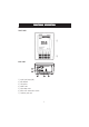
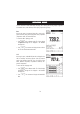
FUNCTIONAL DESCRIPTION HI 4321 DESCRIPTION FRONT PANEL REAR PANEL 1) 2) 3) 4) 5) 6) 7) Liquid Crystal Display (LCD) Main Keyboard USB connector ON/OFF switch Power adapter socket RS232 serial communication connector Conductivity probe input 5
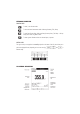
KEYBOARD DESCRIPTION FUNCTION KEYS To enter / exit calibration mode. To select the desired measurement mode: Conductivity, Resistivity, TDS, Salinity. To enter Setup (System Setup, Conductivity Setup, Resistivity Setup , TDS Setup or Salinity Setup) and to access Log Recall function. To obtain general informations about the selected option / operation.
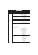
SPECIFICATIONS HI 4321 0.000 to 9.999 µ S/cm 10.00 to 99.99 µ S/cm 100.0 to 999.9 µ S/cm 1.000 to 9.999 m S/cm 10.00 to 99.99 m S/cm 100.0 to 1000.0 m S/cm Ra n g e Con d u ctivity Resolu tion 0.001 µ S/cm 0.01 µ S/cm 0.1 µ S/cm 0.001 m S/cm 0.01 m S/cm 0.1 m S/cm Accu ra cy ±1% of rea d in g (±0.01 µ S/cm ) Cell con sta n t 0.0500 to 200.
HI 4321 Pra ctica l Sa lin ity Sca le 0.00 to 42.00 p su Ra n g e Na tu ra l Sea Wa ter Sca le 0.00 to 80.00 p p t Percen t Sca le 0.0 to 400.0 % Sa lin ity Resolu tion 0.01 for Pra ctica l Sa lin ity Sca le / Na tu ra l Sea Wa ter 0.1 % for Percen t Sca le Accu ra cy ±1% of rea d in g Ca lib ra tion Percen t Sca le - 1 p oin t (with HI 7037 b u ffer) Ra n g e -20.0 to 120.0 °C -4.0 to 248.0 °F 253.15 to 393.15 K Tem p era tu re Resolu tion 0.1 °C / 0.1 °F / 0.1 K Accu ra cy ±0.2 °C / ±0.
OPERATIONAL GUIDE POWER CONNECTION Plug the 12 Vdc adapter into the power supply socket. Note: These instruments use non volatile memory to retain the meter settings, even when unplugged. PROBE CONNECTION For conductivity, resistivity, TDS or salinity measurements connect a conductivity probe to the DIN connector located on the rear panel of the instrument. INSTRUMENT START UP • Turn the instrument on from the power switch located on the rear panel of the instrument.
DISPLAYING MODES For each measurement mode (Conductivity, Resistivity, TDS or Salinity) the following display configurations are available: Basic, Good Laboratory Practice (GLP), Graph and Log History. Basic Accessing this option, the measured value and its units are displayed on the LCD, along with the temperature value, temperature compensation mode, and minimal GLP data. To choose the Basic displaying mode: • Press while in Measure mode.
Graph Accessing this option, the online graph with currently logged values (Conductivity, Resistivity, TDS or Salinity vs. Seconds) could be displayed. If there is no active log, the previously logged data for the selected parameter will be plotted. Notes: • If no data were logged, the graph displaying mode will not be accessible. • If no automatic log is saved, the offline graph will not be available. To access the offline / online graph: • Press while in Measure mode.
Log History Accessing this option, last logged records will be displayed on the LCD. The log history list also contains the appropriate conductivity / resistivity / TDS / salinity values, the logged temperature, the temperature source, as well as the records time stamp. To access the Log History displaying mode: • Press while in Measure mode. The “Choose Display Configuration” message will be displayed in the Reminder messages area. • Press .
SYSTEM SETUP The System Setup menu allows the user to customize the user interface, consult the meter information, set the external serial communication interface and to restore the manufacturer settings. Accessing System Setup • Press while in Measure mode. . The system setup options will be displayed • Press on the LCD. To access a System Setup option: • Use • Press or to highlight the desired option. to access the selected option.
To set the Beeper: • Use or to select the Beeper option. • Press and use or to highlight the desired beeper associated event you want to modify. and use • Press beeper status option. • Press or to highlight the to confirm your selection and return to the Beeper menu or press to return without changing.
To set the GLP data: • Use or to select the GLP Data option. and use • Press desired option. or to highlight the • Press to edit the desired information. The Text Editor menu will be displayed on the LCD. and to • Enter the desired information by using highlight the desired character. It is also possible to delete the last character by positioning the cursor on the Backspace character ( ) . and pressing • Press to return to the GLP Data menu.
To set the Date & Time: to select the Date & Time option. or • Use and use or • Press desired option you want to modify. • Press to highlight the to confirm your selection. Use and then use and to modify the value with (for Set Date and Time option). For the or other two options press to confirm your selection and select one of the displayed formats with or . • Press to confirm your selection and return to the Date & Time options. • Press to return to the previous mode.
Language This option allows the user to choose the desired language for the user interface. To select the Language: • Use or to select the Language option. • Press and use desired language. • Press or to highlight the to confirm your selection and return to the System Setup menu or press without changing.
Meter Information This option provides general information about the instrument serial number (each instrument has an unique identification serial number), the software version and the factory calibration date and time (for conductivity and temperature). Note: All the instruments are factory calibrated for conductivity and temperature. After one year from last factory calibration, the warning will appear at meter startup to inform the user that a new factory calibration is required.
Conductivity SETUP The Conductivity Setup menu allows the user to set the parameters related to the conductivity measurement. Accessing Conductivity Setup • Press while in Measure mode and then select the Conductivity measure mode. to and then to access Conductivity Setup • Press menu. To access a conductivity setup options: • Use or to highlight the desired option. to access the selected option or to exit • Press setup. The following is a detailed description of the Conductivity Setup option screens.
Save Current Profile To save the current profile: or • Use to select the Profile option. and then select Save Current Profile option. The • Press text editor box will be displayed on the LCD. • Enter the desired profile name by using and to to add it highlight the desired character and then press to the text bar. It is also possible to delete the last character by positioning the cursor on the Backspace character ( ) and pressing . • Press to return to the Profile options.
Delete Profile To delete one of the existing profiles: or to select the Profile option. • Use and use • Press Delete Profile option. or to highlight the • Press the screen. . A list with all customised profiles will appear on • Use or to select the desired profile and press . • Press to return to the previous menu. Reading Mode This option allows the user to select between Direct, Direct/AutoHold, Direct/USP conductivity reading modes.
Temperature From the Temperature menu the user can choose the temperature source and units, as well as the temperature compensation mode, reference temperature and compensation coefficient. To access a Temperature option: or to highlight the Temperature • Use option from the Conductivity Setup menu. • Press to access the Temperature option. Temperature Source To set the temperature source: • Use option.
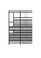
Temperature Compensation The user can choose from the following options: Linear - the meter will compensate automatically the conductivity using the following formula: where: C ref - conductivity at reference temperature Ci - measured conductivity (uncompensated) - compensation coefficient T - temperature ref - reference temperature Non-Linear - recommended for measuring the conductivity of the natural water in accordance with the compensation table on the next page.
Table for non-linear temperature compensation: 0 0 1 2 3 4 5 6 7 8 9 1.918 1.912 1.905 1.899 1.893 1.887 1.881 1.875 1.869 1.863 1 1.857 1.851 1.845 1.840 1.834 1.829 1.822 1.817 1.811 1.805 2 1.800 1.794 1.788 1.783 1.777 1.772 1.766 1.761 1.756 1.750 3 1.745 1.740 1.734 1.729 1.724 1.719 1.713 1.708 1.703 1.698 4 1.693 1.688 1.683 1.678 1.673 1.668 1.663 1.658 1.653 1.648 5 1.643 1.638 1.634 1.629 1.624 1.619 1.615 1.610 1.605 1.
Temperature Unit The user can choose from the Celsius, Fahrenheit or Kelvin temperature units. To set the temperature unit: • Use option. or to highlight the Temperature Units and then use or • Press Celsius, Fahrenheit or Kelvin degrees unit. to select • Press to confirm your selection or press cancel operation. to Reference Temperature (only for linear or non-linear temperature compensation) To set the reference temperature: or • Use perature option.
Compensation Coefficient (only for linear temperature compensation) To set the compensation coefficient: or • Use Coefficient option. • Press using to highlight the Compensation and set the desired compensation coefficient or to increase / decrease the value. to save the current value or press • Press cancel operation. to Calibration / Cell Constant The conductivity probe can be calibrated using the conductivity standards or by entering the cell constant of the probe by the user.
Calibration Points The user can choose between Single Point and Multi Points calibration. To select the calibration points type: or to highlight the Calibration Points • Use option. to confirm your selection and then use • Press or to choose the desired option. • Press to confirm your selection or press cancel operation. to Cell constant manual editing The conductivity probe can also be calibrated by entering the cell constant value.
Calibration Reminder This option allows the user to set the calibration reminder as Daily, Periodic or Disabled. To set the calibration reminder: or to highlight the Calibration re• Use minder option. to confirm your selection and then use • Press or to choose the desired option. • Press to confirm your selection or press cancel operation. to Set Reminder Period Daily reminder - the user can set the time from the day when the reminder is to appear.
Clear Calibration Accessing this option, the existent conductivity calibration can be cleared (the probe cell constant will be reset to default). If the calibration is cleared, another calibration has to be performed. To clear calibration: or to highlight the Clear Calibration option. • Use • Press to clear calibration. A pop-up menu will be displayed asking for confirmation. • Press to confirm or press to escape without saving and return to the Calibration options.
Sample ID This option allows the user to give to the measured samples an identification number/name. Two Sample ID options are available: ID Increment and Edit Sample ID. ID Increment None – the sample ID will be edited alphanumerically by the user. Automatic – the sample ID will be automatically incremented at every new log lot notification. To select the ID increment mode: • Use or to highlight the ID Increment option. and then use or to highlight • Press the desired option.
Log This option allows the user to edit the settings related to the logging feature, as following: Logging Type Three logging types are available: Automatic, Manual and AutoHold. Automatic logging - the readings are logged automatically at constant time intervals (see Sampling Period option). Manual logging ( log on demand)- the readings are logged each time is pressed. AutoHold logging - the readings are logged automatically at each auto-hold event occured.
Sampling Period This option allows the user to select the desired sampling period for automatic logging. To set the sampling period: or to highlight the Sampling Period option. • Use and use or • Press desired option from 1, 2, 5, 10, 30 seconds. to select the to confirm your selection or press • Press cancel operation. to New Lot Accessing this option, the new manually logged readings will be put in a new log lot. To generate a new lot: or to highlight the New Lot option.
Alarm This option allows the user to define two alarm limits for the measurements. Alarm State The following options are available: Disabled – the alarm will be disabled. Inside Limits – the alarm will notify the user when the measured value is inside the preset limits. Outside Limits – the alarm will notify the user when the measured value is outside the preset limits. To set the alarm state: • Use to highlight the Alarm State option. or and use • Press desired option.
Resistivity SETUP The Resistivity Setup menu allows the user to set the parameters related to the resistivity measurements. Accessing Resistivity Setup • Press while in Measure mode and then select resistivity range. to and then to access Resistivity Setup • Press menu. To access a Resistivity Setup option: • Use or to select the desired option. to confirm your selection. • Press The following is a description of the Resistivity Setup option screens. Profile - see Conductivity Setup section.
Temperature - see Conductivity Setup section. Units The user can choose between Ohm, KOhm, MOhm, AutoRanging measuring modes. To select the units: • Use or to highlight the Units option. • Press to confirm and then use to highlight the desired unit. • Press to confirm or press or to cancel operation. Sample ID - see Conductivity Setup section. Log - see Conductivity Setup section. Alarm - see Conductivity Setup section.
TDS SETUP The TDS Setup menu allows the user to set the parameters related to the TDS measurement. Accessing TDS Setup • Press while in Measure mode and then select TDS range. • Press and then to to access TDS Setup menu. To access a TDS Setup option: • Use or to highlight the desired option. to access the selected option. • Press The following is a description of the TDS Setup option screens. Profile - see Conductivity Setup section. Reading Mode - see Resistivity Setup section.
TDS factor Using this option the user can set the TDS factor. • Use • Press or to highlight the TDS Factor option. to confirm your selection and use or to increase / decrease the value. to confirm your selection or press • Press cancel operation. to Sample ID - see Conductivity Setup section. Log - see Conductivity Setup section. Alarm - see Conductivity Setup section.
Salinity SETUP The Salinity Setup menu allows the user to set the parameters related to salinity measurement and calibration. Accessing Salinity Setup • Press while in Measure mode and then select Salinity range. and then • Press menu. To access an Salinity Setup option: • Use or to to access Salinity Setup to highlight the desired option. • Press to access the selected option. The following is a description of the Salinity Setup options. Profile - see Conductivity Setup section.
Clear Calibration Accessing this option, the existent salinity calibration (Percent Scale only) can be cleared. To clear calibration: • Use to highlight the Clear Calibration option. or • Press to clear calibration. A pop-up menu will be displayed to ask for confirmation. • Press to confirm or press to cancel operation. Salinity Scale The meter uses three salinity scales: Natural Sea Water 1966, Practical Scale 1978, Percent Scale [%].
CONDUCTIVITY CALIBRATION It is recommended to calibrate the instrument frequently, especially if high accuracy is required. The conductivity range should be recalibrated: • Whenever the conductivity probe is replaced. • At least once a week. • Before USP measurements. • After testing aggressive chemicals. • When calibration reminder is activated (“Conductivity Cal Expired”). • If the readings are far from the calibration point.
• Insert and rinse the probe in the first beaker in order to decontaminate it; • Insert the probe in the second beaker; • Tap the probe repeatedly to remove any air bubbles that may be trapped inside the sleeve. • Enter in calibration mode by pressing ; • Wait to stabilize; • When the automatic standard recognition is selected, the calibration point will be automatically selected from the Hanna standard list (84 µS, 1413 µS, 5.0 mS,12.88 mS, 80.0 mS, 111.8 mS).
CONDUCTIVITY MEASUREMENT Make sure the instrument has been calibrated before taking conductivity measurements. DIRECT MEASUREMENT To measure the conductivity of a sample using the Direct reading mode: • Press and then to select conductivity measure mode. • Select the Direct reading mode (see Conductivity Setup). • Submerge the conductivity probe and tap it repeatedly to remove any air bubbles that may be trapped inside the sleeve. Allow time for the reading to stabilize.
DIRECT/USP MEASUREMENT In this measure mode the user can check for ultra pure water using the United States Pharmacopeia standard (USP <645>). This USP standard consists of three stages (one in-line and two off-line tests) as following: Stage 1 - this is an in-line test. Test steps: • Measure the temperature of the water and the uncompensating conductivity readings. The measurement may be performed in a suitable container or as in-line measurement.
Stage 3 - this is an off-line test. Test steps: • Take the water sample from the previous stage and increase its ionic strength for a pH measurement at 25 °C; • Record the pH and round it to the nearest 0.1 pH; • Look up the corresponding conductivity value measured in Stage 2 above; • If the conductivity is lower than the conductivity from the below table, then the sample has met the USP requirements. Otherwise, the water didn’t meet the USP requirements. pH 5.0 5.1 5.2 5.3 5.4 5.5 5.6 5.7 5.8 5.9 6.
RESISTIVITY MEASURE MENT Make sure the instrument has been calibrated on conductivity before taking resistivity measurements. DIRECT MEASUREMENT To measure the resistivity of a sample using the Direct reading mode: and then to select resistivity measure • Press mode. • Select the Direct reading mode (see Resistivity Setup section). • Proceed as for the conductivity measurement (see Conductivity Measurement section).
TDS MEASURE MENT Make sure the TDS factor has been set before taking TDS measurements (see TDS Setup section). DIRECT MEASUREMENT To measure the TDS of a sample using the Direct reading mode: and then to select TDS measure mode. • Press • Select the Direct reading mode (see TDS Setup section). • Proceed as for the conductivity measurement (see Conductivity Measurement section).
SALINITY CALIBRATION Salinity calibration is a one-point procedure at 100.0% NaCl. Use the HI 7037L calibration solution (sea water solution) as a 100% NaCl standard solution. To enter salinity calibration: • Set the meter for salinity range; • Select the Percent Scale (see Salinity Setup section); • Rinse the probe with some of the calibration solution or deionized water; • Immerse the probe into HI 7037L solution. The sleeve holes must be completely submerged.
SALINITY MEASURE MENT Three measurement scales are available for salinity (Natural Sea Water Scale, Practical Salinity Scale and Percent Scale). NATURAL SEA WATER SCALE (UNESCO 1966) According to the definition, salinity of a sample in ppt is calculated using the following formula: where: RT - coefficient; CT(sample) - uncompensated conductivity at T °C; C(35,15)= 42914 µS/cm - the corresponding conductivity of KCl solution containing a mass of 32.
PRACTICAL SALINITY SCALE (UNESCO 1978) According to the definition, salinity of a sample in psu (practical salinity units) is calculated using the following formula: where: RT - coefficient; CT(sample) - uncompensated conductivity at T °C; C(35,15)= 42914 µS/cm - the corresponding conductivity of KCl solution containing a mass of 32.4356 g KCl / 1 Kg solution; rT - temperature compensation polynom a0=0.008 b0=0.0005 a1=-0.1692 b1=-0.0056 a2=25.3851 b2=-0.0066 a3=14.0941 b3=-0.0375 a4=-7.0261 b4=0.
TEMPERATURE CALIBRATION The temperature user calibration menu can be accessed at the meter startup by pressing simultaniously three keys as in the below drawing: Note: The temperature user calibration is performed in three points: around 0°C, 50°C, 100°C. To start temperature user calibration: • Insert the probe in the beaker with water at 0°C. • Press to start the temperature calibration. Adjust the temperature preset value using necessary.
LOGGING This feature allows the user to log conductivity, resistivity, TDS, salinity and temperature. The logging behaviour is dependent on the Logging Type and Reading Mode options from the parameter setup. The Logging Data Configuration options from the appropriate parameter setup must be set first in order to be saved into the log report.
to enter log interval edit menu and use • Press or to adjust the logging start-stop time or the log sampling. Press or • Press to save the current value and use to adjust next / previous parameter. to exit log interval edit menu and then press to save the current log. • While the instrument is saving the data, a “Please wait...” pop-up message will be displayed on the LCD. LOGGING MODE 2 This logging mode can be used for multiple samples measurement.
LOGGING MODE 3 This logging mode can be used for any sample measurements. By will be available in Measure choosing this logging mode, mode. To log data using this mode: while in Measure mode to manually log a • Press record. The “Logged” indicator will be displayed on the LCD. • The records will be stored in one lot. In order to change the logging lot, see the measured parameter setup for details, Log option, New Lot generation. LOGGING MODE 4 This logging mode can be used for multiple samples measurement.
. • To stop the logging session, press Notes: • For the automatic logging, if the maximum logging time (24h) has been reached, a warning pop-up will be displayed on the LCD in order to save the current log and start another one in a new lot. • If 100 lots have been saved or maximum 10000 records have been manually stored, a warning pop-up will be displayed on the LCD in order to delete one lot or to select a new lot for the manual logging to log other records.
• Press to return to the previous menu. To delete lots: • Press while in Log Recall mode. • Press or mode. Otherwise, press mode. to access delete or delete all to return to Log Recall view • After selecting one of the deleting modes, use or to select one lot and then press or to delete the selected lot or all lots. The “Please wait...” message will be displayed on the LCD until the selected lot or all lots are deleted.
PC INTERFACE Data transmission from the instrument to the PC can be done with the HI 92000 Windows® compatible software (optional). HI 92000 also offers graphing and on-line help feature. Data can be exported to the most popular spreadsheet programs for further analysis. HI 4321 instrument has two available serial interfaces: RS232 and USB. The desired serial interface can be selected from the settings window of the HI 92000 software.
TROUBLESHOOTING GUIDE SYMPTOMS PROBLEM SOLUTI ON Reading fluctuates up and down (noise). Conductivity probe not properly connected. Insert the probe correctly into the connector. D isplay shows "-----" during measurements. Reading out of range. Recalibrate the meter; Check the sample is within the measurable range. Meter fails to calibrate or gives faulty readings. Broken Conductivity probe. Replace the probe. The instrument doesn't measure the temperature from the probe.
ACCESSORIES CONDUCTIVITY BUFFER SOLUTIONS HI 70033P 84 µS/cm (µmho/cm), 20 mL sachets (25 pcs.) HI 7033M 84 µS/cm (µmho/cm), 230 mL bottle HI 7033L 84 µS/cm (µmho/cm), 500 mL bottle HI 8033L 84 µS/cm (µmho/cm), 500 mL FDA approved bottle HI 70031P 1413 µS/cm (µmho/cm), 20 mL sachets (25 pcs.) HI 7031M 1413 µS/cm (µmho/cm), 230 mL bottle HI 7031L 1413 µS/cm (µmho/cm), 500 mL bottle HI 8031L 1413 µS/cm (µmho/cm), 500 mL FDA approved bottle HI 70039P 5000 µS/cm (µmho/cm), 20 mL sachets (25 pcs.
RECOMMENDATIONS FOR USERS Before using these products, make sure they are entirely suitable for the environment in which they are used. Operation of these instruments in residential areas could cause unacceptable interferences to radio and TV equipment, requiring the operator to follow all necessary steps to correct interferences. The glass bulb at the end of the pH electrode is sensitive to electrostatic discharges. Avoid touching this glass bulb at all times.
SALES AND TECHNICAL SERVICE CONTACTS Australia: Tel. (03) 9769.0666 • Fax (03) 9769.0699 China: Tel. (10) 88570068 • Fax (10) 88570060 Egypt: Tel. & Fax (02) 2758.683 Germany: Tel. (07851) 9129-0 • Fax (07851) 9129-99 Greece: Tel. (210) 823.5192 • Fax (210) 884.0210 Indonesia: Tel. (21) 4584.2941 • Fax (21) 4584.2942 Japan: Tel. (03) 3258.9565 • Fax (03) 3258.9567 Korea: Tel. (02) 2278.5147 • Fax (02) 2264.1729 Malaysia: Tel. (603) 5638.9940 • Fax (603) 5638.9829 Singapore: Tel. 6296.