Instruction Manual HI 2400 Dissolved Oxygen Bench Meter w w w. h a n n a i n s t .
Dear Customer, Thank you for choosing a Hanna Instruments product. Please read this instruction manual carefully before using this instrument. This manual will provide you with the necessary information for correct use of this instrument, as well as a precise idea of its versatility. If you need additional technical information, do not hesitate to e-mail us at tech@hannainst.com.
PRELIMINARY EXAMINATION Remove the instrument from the packing material and examine it carefully to make sure that no damage has occured during shiping. If there is any damage, notify your Dealer or the nearest Hanna Customer Service Center. Each instrument is supplied with: • HI 76407/2 DO probe with 2 m (6.
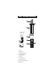
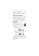
PROBE FUNCTIONAL DESCRIPTION 3 1 4 4 7 5 8 2 6 10 9 1. DO Probe 2. Protective Cap 3. Watertight Shielded Cable 4. Polypropylene Probe Body 5. Temperature Sensor 6. O-Ring Seal 7. Silver Chloride Anode 8. Platinum Cathode (sensor) 9. Oxygen Permeable PTFE Membrane 10.
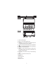
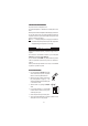
FUNCTIONAL DESCRIPTION Front Panel Rear Panel 1) Liquid Crystal Display (LCD). 2) CAL key, to enter and exit calibration mode. 3) CFM/GLP key, to confirm calibration selection, different setup values or to display Good Laboratory Practice information. 4) ºC key, to manually increase temperature value or other parameters. 5) ºC key, to manually decrease temperature value or other parameters. 6) SETUP key, to enter/exit SETUP mode.
SPECIFICATIONS 0.00 to 45.00 ppm RANGE 0.0 to 300.0% 0.0 to 50.0 ºC (32.0 to 122°F) 0.01 ppm RE SOLUTION ACCURACY @ 20 °C / 68 °F Typical E MC D eviation D O Calibration 0.1% 0.1 °C ±1.5% of full scale or ±1 digit, whichever is greater ±0.2 ºC (excluding probe error) ±1.5% of full scale ±0.
OPERATIONAL GUIDE POWER CONNECTION Plug the 12 VDC adapter into the power supply socket. Notes: • This instrument use non volatile memory to retain the calibration parameters and all the other settings even when unplugged. • Make sure a fuse protects the main line. PROBE CONNECTION AND PREPARATION To take measurements, connect the DO probe to the meter securely by aligning the pins with the socket located on the back of the meter, pushing the plug in and tightening the threaded ring.
INSTRUMENT START-UP • Turn the instrument on by pressing the ON/OFF switch. • All LCD tags are displayed and a beep is generated while the instrument performs a self test. • The instrument will display “ ” blinking until initialization is complete. • After a few seconds “Cond” message appears on the LCD to inform the user that the probe is in auto-conditioning (automatic polarization) mode. • When this message disappears, the probe is polarized and the instrument can be calibrated.
For an accurate calibration, it is recommended to wait at least 15 minutes to ensure precise conditioning of the probe. Keep the protective cap on during polarization time and remove it for calibration and measurements. Follow the calibration procedure (see page 10).
TEMPERATURE MEASUREMENTS The probe has a built-in temperature sensor. The measured temperature is indicated on the secondary LCD as shown above. Allow the probe to reach thermal equilibrium before taking any measurement. This can take several minutes. The greater the difference between the temperature at which the probe was stored and the temperature of the sample, the longer the time will be. Note: If “----” is displayed, the DO probe is not properly connected.
ZERO CALIBRATION • Submerse the probe into HI 7040 zero oxygen solution and stir gently for 2-3 minutes. • Press CAL. The “~” and “ ” tags will blink on the LCD until the reading is stable. • When the reading is stable, “CFM” starts blinking. Press CFM to confirm the “0.0%” DO calibration. • If the reading is within the limits (±15% f.s.), the meter stores the value (and adjusts the slope point). • Press CAL. The instrument will return to measurement mode and will memorize the zero calibration data.
• The instrument stores the slope calibration data and returns to measurement mode. Notes: • If the reading is not close to the selected value, “WRONG“ tag will blink. • If the temperature goes out of range during calibration the “WRONG”, temperature unit tag and both measurements will blink. • HI 2400 has automatic buffer recognition function. If the ARROW keys are pressed to select the desired calibration value, the automatic buffer recognition function is disabled.
GOOD LABORATORY PRACTICE (GLP) GLP is a set of functions that allows storage and retrieval of data regarding the maintenance and status of the system. All data regarding DO calibration is stored for the user to review when necessary. LAST DO CALIBRATION DATA The last DO calibration data is stored automatically after a successful calibration. To view the DO calibration data, press GLP when the instrument is in measurement mode. The instrument will display the time (hh:mm) of the last calibration.
• The instrument ID. SETUP Setup mode allows viewing and modifying the following parameters: • Salinity Factor • Altitude Factor • Log Interval • Current Time (hour & minute) • Current Date (month, day & year) • Beep Status • Instrument ID • Temperature Unit To enter the Setup mode press SETUP while the instrument is in measurement mode. Press SETUP again to exit SETUP mode. Select a parameter with the ARROW keys. Press CAL if you want to change a parameter value. The selected parameter will blink.
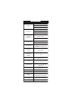
Salinit y (g/l) at Sea Level ºC ºF 0 g /l 10 g /l 20 g /l 30 g /l 35 g /l 0 14.60 13.64 12.74 11.90 11.50 32.0 2 13.81 12.91 12.07 11.29 10.91 35.6 4 13.09 12.25 11.47 10.73 10.38 39.2 6 12.44 11.65 10.91 10.22 9.89 42.8 8 11.83 11.09 10.40 9.75 9.44 46.4 10 11.28 10.58 9.93 9.32 9.03 50.0 12 10.77 10.11 9.50 8.92 8.65 53.6 14 10.29 9.68 9.10 8.55 8.30 57.2 16 9.86 9.28 8.73 8.21 7.97 60.8 18 9.45 8.90 8.39 7.90 7.66 64.4 20 9.
Altitude, Meters above Sea Level ºC 300 600 900 1200 1500 1800 2100 2400 2700 3000 3300 3600 3900 4000 0m m m m m m m m m m m m m m m ºF 0 14.6 14.1 13.6 13.1 12.6 12.1 11.7 11.2 10.8 10.4 10.0 9.7 9.3 9.0 8.9 32.0 2 13.8 13.3 12.8 12.4 11.9 11.5 11.0 10.6 10.2 9.9 9.5 9.2 8.8 8.5 8.4 35.6 4 13.1 12.6 12.2 11.7 11.3 10.9 10.5 10.1 9.7 9.3 9.0 8.7 8.4 8.0 7.9 39.2 6 12.4 12.0 11.5 11.1 10.7 10.3 9.9 9.6 9.2 8.9 8.6 8.2 7.9 7.6 7.5 42.8 8 11.8 11.4 11.0 10.6 10.2 9.8 9.5 9.1 8.
LOG INTERVAL Press CAL when log interval is displayed. The log interval and “CFM” tag is displayed blinking. Press the ARROW keys to change the custom buffer value. Press CFM to confirm the selection. Press CAL to escape without saving. CURRENT TIME Press CAL when the current time is displayed. The hour and “CFM” tag will start blinking. Press the ARROW keys to change the hour. Press RANGE. The minutes will start blinking. Press the ARROW keys to change the minutes. Press CFM to save the modified value.
Press CFM to save the modified value. Press CAL to escape without saving. BEEP STATUS Press CAL when the beep status is displayed. The beep status (“ON” or “OFF”) and “CFM” tag will start blinking. Press the ARROW keys to change the beep status. Press CFM to save the modified value or press CAL to escape without saving. INSTRUMENT ID Press CAL when “InId” is displayed. The instrument ID (“0000“ to “9999“) and “CFM” tag will start blinking. Press the ARROW keys to change the instrument ID value.
LOGGING This function allows the user to log DO (in ppm or %) together with temperature automatically, for long periods of time. All logged data can be stored into a PC through the USB port. The memory used for storing the logged data is divided in 32 pages. The capacity of each page is 250 samples. The lot number goes from 1 to 100. The maximum capacity of the log memory is 8000 samples. Each time a new lot starts, it automatically starts from a new page.
If the log space is full, the “FULL LOG” message will be displayed and no more data will be saved. Note: When pressing any key that is not active, while lot logging is running, the following message is displayed for a few seconds. VIEW LOGGED DATA Press the RCL key while in measurement mode to retrieve the stored information.
• The date on the primary LCD, along with “DATE”, month and day tags. • The salinity on the primary LCD and “SAL” message on the secondary LCD. • The altitude on the primary LCD and “ALt” message on the secondary LCD. • The interval for lot logging. TO DELETE LOTS To delete a lot, use the ARROW keys to select the desired lot. Press CLR key. The “dEL” message is displayed on the primary LCD and the selected lot on the secondary LCD, along with ”RCL” tag.
TEMPERATURE CALIBRATION ( f o r t e c h n i c a l p e r s o n n e l o n l yy)) Each meter has been factory calibrated for temperature with the supplied DO probe and is ready for measurements. The DO probes are interchangeable and no temperature calibration is needed. If the temperature measurements are not accurate, temperature recalibration should be performed. For an accurate recalibration, contact your dealer or the nearest Hanna Customer Service Center, or follow the procedure below.
• Submerse the DO probe in the second vessel as near as possible to the reference thermometer. Allow a few seconds for the probe to stabilize. • Use the ARROW keys to set the reading on the secondary LCD to that of the hot water. • When the reading is stable, the “CFM” tag starts blinking. • Press CFM to confirm. The instrument returns to measurement mode. Note: If the reading is not close to the selected calibration point, “WRONG” tag will blink.
PC INTERFACE Data transmission from the instrument to the PC can be done with the HI 92000 Windows® compatible software (optional). HI 92000 also offers graphing and an on-line help feature. Data can be exported to the most popular spreadsheet programs for further analysis. To connect your instrument to a PC, use a standard USB cable. Make sure that your instrument is switched off and plug one connector to the instrument’s USB socket and the other to the USB port of your PC.
CHR xx Change the instrument range according with the parameter value (xx): • xx=06 % range • xx=07 ppm range The instrument will answer for these commands with: where: is 02 ASCII code character (start of text) is 03 ASCII code character (end of text) : is 06 ASCII code character (recognized command) is 21 ASCII code character (unrecognized command) is 24 ASCII code character (corrupted command) COMMANDS REQUIRING AN ANSWER The instrument will
MDR Requests the instrument model name and firmware code (16 ASCII chars). GLP Requests the calibration data record. The answer string contains: • GLP status (1 char): represents a 4 bit hexadecimal encoding. • 0x04 - DO calibration available • DO calibration data (if available), which contains: • the number of calibrated satandards (1 char) • the calibration time, yymmddhhmmss (12 chars) • standards information • standard value, with sign and decimal point (7 chars).
GLDxxxfff:Requests the records of the “xxx” lot number. The records are sent in frames of 10 records; “fff” is the frame number (01 first frame). (Example: Lot 13 has 53 records. The records will be sent in 6 frame, 5 with10 records and 1 with 3 records.) Command Parameters: xxx - Lot number (eq: for lot number 1 xxx = 001) fff - requested frame number - first frame is labeled 01 Notes: • • • • • • • “Err3” is sent if the Log on demand is empty.
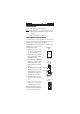
PROBE & MEMBRANE MAINTENANCE The oxygen probe body is made of reinforced plastic for maximum durability. A thermistor temperature sensor provides temperature measurements of the sample. Use the protective probe cap when not in use. To replace the membrane or refill with electrolyte, proceed as follows: • Remove the protective cap by gently twisting and pulling it off the body of the probe (see fig. 1). • Unscrew the membrane cap by turning it counterclockwise (see fig. 2).
Important In order to have accurate and stable measurements, it is important that the membrane surface is in perfect condition. This semipermeable membrane isolates the sensor elements from the environment but allows oxygen to enter. If any dirt is observed on the membrane, rinse carefully with distilled or deionized water. If any imperfections still exist, or any damage is evident (such as wrinkles or tears-holes), the membrane should be replaced.
ACCESSORIES HI 7040M Zero Oxygen Solution, 230 ml HI 7040L Zero Oxygen Solution, 500 ml HI 7041S Refilling Electrolyte Solution, 30 ml HI 710005 115VAC to 12VDC converter HI 710006 230VAC to 12VDC converter HI 76407/2 Spare probe with 2 meters (6.
RECOMMENDATIONS FOR USERS Before using this product, make sure that it is entirely suitable for the environment in which it is used. Operation of this instrument in residential areas could cause unacceptable interferences to radio and TV equipment, requiring the operator to follow all necessary steps to correct interferences. During operation, ESD wrist straps should be worn to avoid possible damage to the electrode by electrostatic discharges.
Hanna Instruments Inc. Highland Industrial Park 584 Park East Drive Woonsocket, RI 02895 USA Technical Support for Customers Tel. (800) 426 6287 Fax (401) 765 7575 E-mail tech@hannainst.com www.hannainst.