HI 23 / HI 24 Series Wall-mounted, Microprocessor-based, Conductivity and TDS Process Controllers Instruction Manual 1
Dear Customer, Thank you for choosing a Hanna Product.
TABLE OF CONTENTS PRELIMINARY EXAMINATION ............................................4 GENERAL DESCRIPTION ................................................. 4 MAIN FEATURES OF DIFFERENT MODELS ......................... 5 FUNCTIONAL DESCRIPTION ............................................7 MECHANICAL DIMENSIONS ............................................9 SPECIFICATIONS .......................................................... 10 INSTALLATION ..............................................................
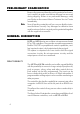
PRELIMINARY EXAMINATION Remove the instrument from the packing material and examine it carefully to make sure that no damage has occurred during shipping. If there is any noticeable damage, notify your Dealer or the nearest Hanna Customer Service Center immediately. Note Save all packing materials until you are sure that the instrument functions correctly. Any damaged or defective items must be returned in their original packing materials together with the supplied accessories.
MAIN FEATURES OF DIFFERENT MODELS • Display: large LCD with 4 ½ 13 mm digits and 3 ½ 7.7 mm digits. • LEDs: four LEDs are provided for signaling the energizing of relays 1 and 2 (yellow LEDs) and alarm relay (a green and a red LED). • Relays: 2 output relays for low conductivity or high conductivity dosage (COM, NO and NC contacts) and 1 output relay for alarm condition (COM, NO and NC contacts).
• Calibration and Setup procedures allowed only through an unlock password. • Calibration: 2 points with Hanna EC and TDS calibration solutions. • Four different EC working ranges (0 to 199.9µS; 0 to 1999µS; 0 to 19.99mS; 0 to 199.9mS). • Four different TDS working ranges (0 to 100.0ppm; 0 to 1000ppm; 0 to 10.00ppt; 0 to 100.0ppt) for HI 24 series. • Possibility to switch to TDS measurements with conversion factor from 0.00 to 1.00 (HI 24 series). • Temperature compensation of the HANNA standard solutions.
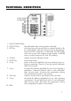
FUNCTIONAL DESCRIPTION 1. Liquid Crystal Display 2. CAL DATA key last calibration data viewing (enters and exits) 3. LCD key exits from setup and reverts back to normal mode (in idle or control phases with the measurement on the display). During EC/TDS calibration, it alternates EC/TDS buffer value and current cell constant on the display. In HI 24 series, it switches between EC and TDS reading 4. CAL key initiates and exits calibration mode 5. SETUP key enters setup mode 6.
1. 2. 3. 4. 5. 6. 7. 8. 9. 10. 11. 12. RS 485 communications terminal (HI 23xy2 and HI 24xy2 models only) Analog Output terminal (HI 23xy1 and HI 24xy1 models only) Pt 100 Temperature Sensor terminal Power supply output for external transmitter 4-20 mA input from external transmitter Main Power Supply Alarm Terminal Contact 1 - First Dosing Terminal Contact 2 - Second Dosing Terminal EC/TDS probe connector Hold terminal Timer terminal Unplug the meter before any electrical connection.
MECHANICAL DIMENSIONS 9
SPECIFICATIONS Ranges 0.0 to 199.9 µS/cm, 0 to 1999 µS/cm 0.00 to 19.99 mS/cm, 0.0 to 199.9 mS/cm 0.0 to 100.0 ppm, 0 to 1000 ppm (HI 24* series only) 0.00 to 10.00 ppt, 0.0 to 100.0 ppt (HI 24* series only) -10.0 to 100.0 °C Resolution 0.1 µS/cm, 1 µS/cm 0.01 mS/cm, 0.1 mS/cm 0.1 ppm, 1 ppm (HI 24 series only) 0.01 ppt, 0.1 ppt (HI 24 series only) 0.1 °C Accuracy ±0.5 % full scale (EC and TDS) ±0.
INSTALLATION HI 23 and HI 24 series offer a multitude of possibilities, from dual setpoints to ON/OFF or PID dosage, isolated outputs with user-selectable zoom, recorder outputs in mA and volts. Use the 3-wire Pt 100 temperature sensor to compensate for the cable resistance and have a precise automatic temperature compensation of the measurements in long distance applications. See the below diagram for a recommended installation.
• Power Supply: Connect a 3-wire power cable to the terminal strip, while paying attention to the correct line (L), earth (PE) and neutral (N) terminal connections. Power: 230VAC - 50 mA. Line Contact: 200mA fuse inside. PE leakage current 1 mA; this contact must be connected to ground. • Conductivity input: the default input is from conductivity probe. Connect the EC probe to the terminals #10 on page 8. HI7639D is a conductivity probe with built-in temperature sensor.
If the Pt 100 has more than 2 wires, connect the two wires of one end to pins 9 and 10 (pin 9 is an auxiliary input to compensate for the cable resistance) and one wire from the other end to pin 8. Leave the fourth wire unconnected, if present. Note If the meter does not detect the temperature probe, it will switch automatically to manual temperature compensation with the temperature adjustable through the up and down arrow keys. The “°C” symbol will blink on the LCD.
Connect the two signal wires from the transmitter to terminals #5 on page 8, paying attention to the correct polarity. Terminal 14 is the positive input and terminal 15 is the negative input. An unregulated 10 ÷ 30 VDC - 50 mA max. power supply output (#4 on page 8) is provided to power the transmitter, if needed. Pin 12 is the positive voltage terminal and pin 13 is the negative voltage terminal.
The setup codes can be selected after password and CFM are pressed. When CFM is pressed, the current setup item is saved on EEPROM and the following item is displayed. Whenever LCD is pressed, the device reverts back to control mode. The same is true when CFM is pressed on the last setup item. The possible transitions in setup mode are the following: ENTERING THE PASSWORD • Press SETUP to enter the setup mode. The LCD will display “0000” on the upper part and “PAS” on the lower.
Note The default password is set at “0000”. • The LCD will display “SET” on the upper part and “c.00” on the lower, allowing the user to edit setup parameters (see table below). • Using the arrow keys as for the above password procedure, enter the code of the parameter to set, e.g. 41. • Confirm the code by pressing CFM and the default or the previously memorized value will be displayed with the first digit blinking.
SETUP CODES The following table lists the setup codes along with the description of the specific setup items, their valid values and whether password is required to view that item (“PW” column): Code Valid Values Default PW 00 Factory ID 0 to 9999 0000 no 01 Process ID 0 to 99 00 no 02 Control enable/disable 0: C.M. disabled 1: C.M. enabled 0 no 03 Range 1: 0.0-199.9 µS (or 100.0 ppm) 4 (depends on model) 2: 0-1999 µS (or 1000 ppm) 3: 0.00-19.99 mS (or 10.00 ppt) 4: 0.0-199.9 mS (or 100.
Code Valid Values Default PW 21 Relay 2 mode (M2) same as relay 1 0 no 22 Relay 2 setpoint (S2) 0.5 to 99.5% full scale 75% f.s. no 23 Relay 2 hysteresis (H2) 0 to 5% f.s. 1% f.s. no 24 Relay 2 deviation (D2) 0.5 to 10% f.s. 1% f.s. no 25 Relay 2 reset time 0.1 to 999.9 minutes 999.9 no 26 Relay 2 rate time 0.0 to 999.9 minutes 0.0 no 30 Alarm relay High Alarm (HA) 0.5 to 99.5% full scale 95% f.s. no HA-HysULA+Hys,Hys=1.5%f.s.
Note Code Valid Values Default PW 71 Baud rate 1200, 2400, 4800, 9600 4800 yes 72 Cleaning timer 0 to 19999 days 0 no 73 Initial cleaning day 01 to 31 01 no 74 Initial cleaning month 01 to 12 01 no 75 Initial cleaning year 1998 to 9999 1998 no 76 Initial cleaning time 00:00 to 23:59 00:00 no 77 Cleaning ON interval 0 to 19999 minutes 0 no 90 Display selftest 1: on 0: off 0 yes 91 Keyboard selftest 1: on 0: off 0 yes 92 EEPROM selftest 1: on 0: off 0 yes 93 Relays
If M2= 1 then S2-H2ULA; If M2= 2 then S2+H2THA; If M2= 3 then S2+D2THA; If M2= 4 then S2-D2ULA; If M1= 1 and M2 = 2 then S1-H1US2+H2, S2ULA, HAUS1; If M1 = 2 and M2 = 1 then S2-H2US1+H1, S1ULA, HAUS2; If M1 = 3 and M2 = 2 then S1US2+H2, S2ULA, HAUS1+D1; If M1 = 2 and M2 = 3 then S1+H1TS2, S1ULA, HAUS2+D2; If M1 = 4 and M2 = 1 then S1TS2–H2, S1–D1ULA, HAUS2; If M1 = 1 and M2 = 4 then S1–H1US2, S2–D2ULA, HAUS1; If M1 = 3 and M2 = 4 then S1US2, S2–D2ULA, HAUS1+D1; If M1 = 4 and M2 = 3 then S2US1, S1–D1ULA, HAU
CONTROL MODE The control mode is the normal operational mode for these meters. During control mode the meter fulfills the following main tasks: • converts information from EC/TDS and temperature inputs to digital values; • control relays and generates the analog outputs as determined by the setup configuration, displays alarm condition; In the HI 24 series it is possible to switch between EC and TDS reading pressing “LCD”.
An upper boundary is imposed for dosage time when relays are energized continuously, i.e. when relay works in ON/ OFF mode or also in PID mode but in the latter case only if the relay is always ON. This parameter can be set through the setup procedure. When the maximum boundary is reached, an alarm is generated; the device stays in alarm condition until relay is de-energized.
de-energized when the EC value is above the setpoint plus the hysteresis. ON OFF Setpoint Setpoint + Hysteresis EC The low setpoint relay may be used to control a low conductivity dosing pump. P.I.D. CONTROL MODE (HI 23x2z and HI 24x2z models only) PID control is designed to eliminate the cycling associated with ON/OFF control in a rapid and steady way by means of the combination of the proportional, integral and derivative control methods.
The derivative function (rate action) compensates for rapid changes in the system reducing undershoot and overshoot of the EC or TDS value. During PID control, the ON interval is dependent not only on the error amplitude but even on the previous measurements. Definitely PID control provides more accurate and stable control than ON/OFF controllers and it is best suitable in system with fast response, quickly reacting to changes due to addition of low or high conductivity solution.
second is the integrative action and the third is the derivative action. Proportional action can be set by means of the Proportional Band (PB). Proportional Band is expressed in percentage of the input range and is related to Kp according to the following: 100% Controller output 0 Error Proportional Band Kp = 100/PB. The proportional action is set through the setup procedure as “Deviation” in percent of full scale of the selected range.
The user can vary five different parameters, i.e. the setpoint (S1 or S2), the deviation (D1 or D2), the reset time, the rate time and the proportional control mode period Tc (from 1 to 30 minutes). Note User can disable the derivative and/or integrative action (for P or PI controllers) by setting Td = 0 and/or Ti = MAX (Ti) respectively through the setup procedure. SIMPLE TUNING PROCEDURE The following procedure uses a graphical technique of analyzing a process response curve to a step input. 1.
4. The deviation, Ti and Td can be calculated from the following: • Deviation = Tx * max. slope (EC/TDS) • Ti = Tx / 0.4 (minutes) • Td = Tx * 0.4 (minutes). 5. Set the above parameters and restart the system with the controller in the loop. If the response has too much overshoot or is oscillating, then the system can be fine-tuned slightly increasing or decreasing the PID parameters one at a time. Note Connecting an external device (e.g.
Moreover the alarm signal is generated only after a user selectable time period (alarm mask) has elapsed since the controlled value has overtaken one alarm threshold. This additional feature will avoid fake or temporary alarm conditions. Note If the power supply is interrupted, the relay is de-energized as if in alarm condition to alert the operator. In addition to the user-selectable alarm relays, all EC/TDS controllers are equipped with the Fail Safe alarm feature.
Note In order to have the Fail Safe feature activated, an external power supply has to be connected to the alarm device. CONTROL THROUGH ANALOG OUTPUT Models HI 23xy1 and HI 24xy1 have a proportional analog output signal (selectable among 0-1mA, 0-20mA, 4-20mA, 0-5VDC, 1-5VDC and 0-10VDC) at the analog output terminals. With this signal, the actual output level amplitude is varied, rather than the proportion of ON and OFF times (duty cycle control). A device with analog input (e.g.
Control actions are stopped as soon as the user presses SETUP and enters the password. In order to reactivate the control mode, use code 02 of setup (see “Setup” section). Otherwise, the meter remains in idle mode. ANALOG OUTPUT Models HI 23xy1 and HI 24xy1 are provided with the analog output feature. The output is galvanic separated and can be a voltage or a current. Pin 5 is the voltage output, pin 6 is the analog output common and pin 7 is the current output.
The type (voltage or current) and the range of the output analog signal is selectable through the jumpers on the board. Analog output options are as follows: 0-5 VDC; 1-5 VDC 0-10 VDC (default) 0-20 mA; 4-20 mA (default) 0-1 mA Note Note Note Choice between different ranges with the same configuration (for example 0-20 mA and 4-20 mA) is achieved via software by entering the setup mode and selecting code 40 (see Setup Mode section for exact procedure).
CALIBRATION The controller is factory calibrated for temperature as well as for the analog input and outputs. The user should periodically calibrate the instrument for EC or TDS. For greatest accuracy, it is recommended that the instrument is calibrated frequently. Before beginning normal operation, it is recommended to standardize the probe with the Hanna calibration solution close to the expected sample value and inside the selected range.
To obtain accurate readings, use the calibration solution in the selected range and closer to the values to be measured. Offset Calibration • To perform the EC or TDS calibration enter the calibration mode, by pressing CAL and entering the password. • After the correct password is entered, the control actions stop and the primary LCD will display the first EC or TDS calibration value, with the "CAL" indicator blinking. The secondary LCD displays the temperature.
• When the reading is stable, "CAL" will stop flashing (after about 30 seconds) and "CFM" indicator will blink. • Press CFM to confirm the calibration point; if the reading is close to the selected solution, the meter stores the reading. If the reading is not close to the selected solution, "ERROR" will blink. A 2-point calibration is always suggested. However the EC/ TDS calibration can also be performed at 1 point.
CELL CONSTANT DIRECT SELECTION Whenever the EC/TDS probe cell constant is known, it is possible to directly calibrate the meter using that value. • Press CAL to enter calibration mode. The LCD will show 0. • Press LCD to display the current cell constant on the primary LCD (factory default value is 2.000 cm-1). • Press SETUP key. • Using , and , enter the probe cell constant (the value must be between 1.333 and 4.000 cm-1) and confirm by pressing CFM.
Note Note Press SETUP before CFM to exit without changes. It is suggested to calibrate the offset before entering the calibration buffer direct selection. TEMPERATURE CALIBRATION The controller is factory calibrated for temperature. However, the user may also perform a one point temperature calibration. This procedure is to calibrate the offset only; the slope will remain as factory calibrated. • Prepare a beaker containing a solution at a given temperature inside the range of the meter.
Calibration procedure may be interrupted by pressing CAL again at any time. If the calibration procedure is stopped this way, or if the controller is switched off before the last step, no calibration data is stored in nonvolatile memory (EEPROM). ANALOG INPUT CALIBRATION The analog input is already factory calibrated. However, the user may also perform a 2-point calibration at 4 and 20 mA. It is sufficient to perform the calibration on one range only. • Connect a mA simulator (e.g.
• Press CFM to confirm. The meter will return to normal operational mode. Calibration procedure may be interrupted by pressing CAL again at any time. If the calibration procedure is stopped this way, or if the controller is switched off before the last step, no calibration data is stored in nonvolatile memory (EEPROM). ANALOG OUTPUT CALIBRATION In the models where the analog output is available, this feature is factory calibrated through software. The user may also perform these calibration procedures.
TYPE OUTPUT CODE CALIBRATION POINT 1 CALIBRATION POINT 2 CALIBRATION 0-1 mA 0 0 mA 1 mA 0-20 mA 1 0 mA 20 mA 4-20 mA 2 4 mA 20 mA 0-5 VDC 3 0 VDC 5 VDC 1-5 VDC 4 1 VDC 5 VDC 0-10 VDC 5 0 VDC 10 VDC • Press CFM to confirm the selected parameter that will stop blinking on the primary display. The secondary display shows the HI 931002 or multimeter input value as lower limit of the interval.
Note When adjusting values using the or keys it is important to allow for sufficient response time (up to 30 seconds) The table below lists the values of output codes along with the calibration point values (which are the analog output minimum and the analog output maximum) as indicated on the display. The secondary display indicates the current calibration point value, while the primary display indicates the current calibration type.
• Press or to cycle through the data forward or backwards respectively. Note In any moment, by pressing LCD or CAL DATA the meter will return to the regular operating display. • Press or to view the time of last calibration. The secondary display will show "HOU". • Press or again to view the cell constant at the time of the last calibration. The secondary display will show "CEL". • Press or again to return to the first CAL DATA display (date) at the time of last calibration.
A I2C failure is detected when the I2C transmission is not acknowledged or a bus fault occurs for more than a certain number of attempts (this can be due, for example, to damage sustained by one of the ICs connected to I2C bus). If so, the controller stops any tasks and displays a perpetual sliding message “Serial bus error” (i.e. this is a fatal error). If an invalid date is read from RTC, it is initialized back to the default date and time (01/01/98 - 00:00).
As soon as one or more keys are pressed, the appropriate segments out of 88:88 corresponding to the pressed keys, will light up on the screen. The correspondence is given below: For example, if UP and CAL are pressed together the LCD will look like this: The colon is a useful indicator for the correct position squares. Note A maximum of two keys may be pressed simultaneously to be properly recognized. To exit the keyboard test procedure press LCD, CAL and SETUP simultaneously.
EEPROM SELFTEST The EEPROM selftest procedure involves verifying the stored EEPROM checksum. If the checksum is correct the “Stored data good” message will be shown for a few seconds before exiting selftest procedure. If not, the message “Stored data error - Press to reset stored data or to ignore”. If is pressed the EEPROM selftest procedure terminates with no other action. Otherwise, EEPROM is reset with de- fault values from ROM as when a device with a virgin EEPROM is switched on.
WATCHDOG When a dead loop condition is detected a reset is automatically invoked. The effectiveness of watchdog capability can be tested through one of the special setup items. This test consists of executing a dummy dead loop that causes watchdog reset signal to be generated. EXTERNAL FUNCTIONS HOLD FUNCTION This function allows to perform the maintenance procedures.
RS 485 COMMUNICATION HI 23xy2 and HI 24xy2 are provided with an RS485 port. RS485 standard is a digital transmission method that allows long lines connections. Its differential transmission system makes this standard suitable for data transmission in noisy environments. SPECIFICATIONS The RS485 standard is implemented in EC process meter controllers with the following characteristics: Data rate: 1200, 2400, 4800 and 9600 bps Communication: Bidirectional Half-Duplex Line length: up to 1.
Up to 32 units can be connected to the same RS485 line, with a total line length of up to 1.2 Km using 24AWG cable. To minimize electromagnetic interference, use shielded or twisted pair cable to connect the units. Each EC controller unit is identified by its process ID number (setup item “01”). The EC controller acts as a “slave” device: it only answers to commands received from a “master” device (e.g. an industrial PC) connected to the line.
• Using the arrow keys, set the controller address. To exit setup, press CFM key and then LCD key. Note In an RS 485 network, each device must have a different address. • Select the desired baud rate with the up and down keys and press the CFM key to store the new settings. Available baud rates are: 1200, 2400, 4800 and 9600 Bps. The PC software to communicate with the controllers is HI92500. Please refer to this product specifications for further informations.
Note KDS null Same as LCD key KDW null Same as key KRG null Same as key KST null Same as SETUP key KUP null Same as key MDR null Request firmware code ECR null Request EC reading (available in control or idle mode only) TDR null Request TDS reading (available in control or idle mode only, for HI 24 series only) RNG null Request measure Range (available in control or idle mode only) TMR null Request temperature reading PWD NNNN Send the 4-digit password SET NNPC1C2C3C4C5 Se
“01SET33+015••” This command sets the setup item 33 (max. relay ON time) of a controller, identified by the process ID number 01, to 15 minutes. The • character means blank.
The time-out for the first character of the controller answer is 100 milliseconds. The minim delay between the last received character and first character of the answer is 15 ms. When the controller answers to the ECR, TDR and TMR commands, the reading is sent as ASCII string followed by a character indicating the control and alarm status of the controller and info for controller setup modified.
“0310.7D” meaning that the current temperature reading is 10.7°C, the control action is active and no alarm condition is present and controller setup is modified (must update controller setup for PC – GET commands for setup items). If asking for the last calibration data and the controller was never calibrated, it answers with “0”; e.g. “010”. If the controller was calibrated, it answers with “1” followed by the calibration data.
STARTUP During the automatic startup the Real Time Clock (RTC) is checked to see if a reset occurred since last software initialization. In this case, the RTC is initialized with the default date and time 01/01/1998 - 00:00. An EEPROM reset does not affect the RTC settings. The EEPROM is also checked to see if it is new. If this is the case, the default values are copied from ROM and then the device enters normal mode.
EC VALUES AT VARIOUS TEMPERATURES Temperature has a significant effect on conductivity. Table below shows EC values at various temperatures for the Hanna calibration solutions. TEMPERATURE °C °F HI7030 HI8030 HI7039 HI8039 0 32 7150 776 64 48300 65400 2760 5 41 8220 896 65 53500 74100 3180 10 50 9330 1020 67 59600 83200 3615 15 59 10480 1147 68 65400 92500 4063 16 60.8 10720 1173 70 67200 94400 4155 17 62.6 10950 1199 71 68500 96300 4245 18 64.
EC / TDS PROBE MAINTENANCE Probe can be compensated for normal contamination by a process of recalibration. When calibration can no longer be achieved, remove the conductivity probe from the system for maintenance. PERIODIC MAINTENANCE Inspect the probe and the cable. The cable used for the connection to the controller must be intact and there must be no points of broken insulation on the cable. Connectors must be perfectly clean and dry. CLEANING PROCEDURE Rinse the probe with tap water.
ACCESSORIES CONDUCTIVITY & TDS CALIBRATION SOLUTIONS HI 7030L 12880 µS/cm (µmho/cm), 460mL HI 7030M 12880 µS/cm (µmho/cm), 230mL HI 7031L 1413 µS/cm (µmho/cm), 460mL HI 7031M 1413 µS/cm (µmho/cm), 230mL HI 7033L 84 µS/cm (µmho/cm), 460 mL HI 7033M 84 µS/cm (µmho/cm), 230 mL HI 7034L 80000 µS/cm (µmho/cm), 460mL HI 7034M 80000 µS/cm (µmho/cm), 230mL HI 7035L 111800 µS/cm (µmho/cm), 460mL HI 7035M 111800 µS/cm (µmho/cm), 230mL HI 7039L 5000 µS/cm (µmho/cm), 460mL HI 7039M 5000 µS/cm (µmho/cm), 230mL HI 7032L
ELECTRODE CLEANING SOLUTIONS HI 7061M General Cleaning Sol., 230 mL HI 7061L General Cleaning Sol., 460 mL ELECTRODE CLEANING SOLUTIONS IN FDA APPROVED BOTTLES HI 8061M General Cleaning Sol., 230 mL HI 8061L General Cleaning Sol.
WARRANTY All Hanna Instruments meters are guaranteed for two years against defects in workmanship and materials when used for their intended purpose and maintained according to instructions. The probes are guaranteed for a period of six months. This warranty is limited to repair or replacement free of charge. Damage due to accident, misuse, tampering or lack of prescribed maintenance are not covered. If service is required, contact the dealer from whom you purchased the instrument.
CE DECLARATION OF CONFORMITY Recommendations for Users Before using these products, make sure that they are entirely suitable for the environment in which they are used. Operation of these instruments in residential areas could cause unacceptable interferences to radio and TV equipment. To maintain the EMC performance of equipment, the recommended cables noted in the user's manual must be used. Any variation introduced by the user to the supplied equipment may degrade the instruments' EMC performance.
MANHI23 10/02 w w 60 w . h a n n a i n s t .