
User Guide


FUNCTIONAL DESCRIPTION
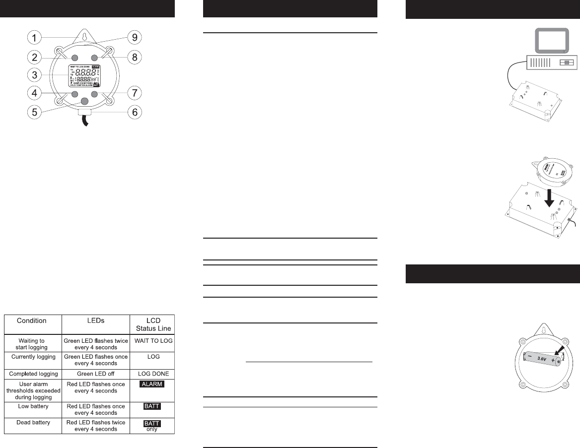
1. Hook*
2. Green LED
3. LCD*
4. Photo LED
5. Internal sensor*
6. Connection for external sensor(s)*
7. Infrared LED
8. Red LED
9. Internal magnetic switch: touch
the top of the meter with magnetic
key for activating magnetic start
* depending on model
The status of the thermologger is indicated by the green and
red LEDs, and optional LCD:
Green LED will light up when magnetic switch is activated by
the key. When the key is removed from the top of the meter,
the green LED switches off.
SPECIFICATIONS
Model Sensor(s) Range
HI 141A (H) T1 internal
-
HI 141B (H) T1 external
-
HI 141C (H)* T1 internal
HI 141D (H) T1 external
HI 141E (H) T1 internal
T2 external
HI 141F (H) T1 external
T2 external
HI 141G (H)* T1 internal
T2 external
HI 141J (H) T1 external
T2 external
* Warning: T1 temperature range is limited by LCD characteristics.
Do not use the logger out of this range.
-40.0 to 80.0ºC
-40.0 to 175.0ºF
-40.0 to 125.0ºC
-40.0 to 257.0ºF
-20.0 to 70.0ºC*
-4.0 to 158.0ºF*
-40.0 to 125.0ºC
-40.0 to 257.0ºF
-40.0 to 80.0ºC
-40.0 to 175.0ºF
-40.0 to 125.0ºC
-40.0 to 257.0ºF
-40.0 to 125.0ºC
-40.0 to 125.0ºC
-40.0 to 257.0ºF
-20.0 to 70.0ºC*
-4.0 to 158.0ºF*
-40.0 to 125.0ºC
-40.0 to 257.0ºF
-40.0 to 125.0ºC
-40.0 to 125.0ºC
-40.0 to 257.0ºF
Resolution 0.1ºC (-40.0 to 100.0ºC); 0.2ºC (temp. >100.0ºC)
0.1ºF (-40.0 to 190.0ºF) ; 0.3ºF (temp. >190.0ºF)
Accuracy
HI 141 HI 141001
EXTERNAL DIAMETER 86.5 mm (3.4”) 159 mm (6.3”)
HEIGHT 35 mm (1.4”) 60 mm (23.6”)
WEIGHT 150 g (5.54 oz.) 200 g (7.39 oz.)
±0.5ºC (-40.0 to 0.0 and 70.0 to 100.0 ºC)
±0.4ºC (0.0 to 70.0 ºC)
±1.0ºC (temperature>100.0ºC)
±1.0ºF (-40.0 to 32.0 and 158.0 to 212.0ºF)
±0.8ºF (32.0 to 158.0 ºF)
±2.0ºF (temperature>212.0ºF)
START UP
In order to communicate with the
HI 141 thermologger, the
HI 141000 application software
must be installed on your PC. This
is done by inserting the first floppy
disk in the driver and running
Setup.exe.
Connect the HI 141001 Infrared
Transmitter to your computer
through an available RS232 port.
Place the HI 141 on the transmit-
ter, taking care to align the ribs
on the logger with the slots on the
transmitter
Run HI 141000 software and re-
fer to the on-line help for any
further information about setting
the parameters of the logger, ac-
quiring logged data, etc.
BATTERY REPLACEMENT
Battery replacement must only take place in a non hazardous
area using the appropriate battery type (3.6V Lithium AA
battery).
When the battery needs to be re-
placed, simply remove the four screws
on the rear cover of the logger and
replace the battery with a new one
paying attention to the correct po-
larity. Replace the cover and tighten
the four screws.
When battery is replaced, both LEDs will turn on, and the Red
LED will then turn off followed by the Green LED. This indicates
that a proper reset of the logger has been done. Should this not
occur, please reinstall the battery.
For loggers with LCD, the LCD will also light up for about 1
second, showing all segments.
Note: Dispose of the Lithium (Li) battery according to local
regulations.
Note: For models with two external sensors, T1 and T2 channels are
indicated on the probes (T1 is red marked, T2 is white).