Instruction Manual HI 120 & HI 122 pH/mV/Temperature Bench Meters with Calibration Check ON OFF HI 122 CAL CFM pH / mV Meter CLR LOG Calibration Check w w w. h a n n a i n s t .
Dear Customer, Thank you for choosing a Hanna Instruments product. Please read this instruction manual carefully before using the instruments. This manual will provide you with the necessary information for correct use of the instruments, as well as a precise idea of their versatility. If you need additional technical information, do not hesitate to e-mail us at tech@hannainst.com or turn to the back cover for our worldwide contact list. These instruments are in compliance with directives.
PRELIMINARY EXAMINATION Remove the instrument from the packing material and examine it carefully to make sure that no damage has occurred during shipping. If there is any damage, notify your Dealer or the nearest Hanna Service Center. Each instrument is supplied with: • HI 1131P Glass-body Combination pH Electrode • HI 7662-T Temperature probe • pH 4.01 & 7.
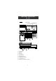
FUNCTIONAL DESCRIPTION HI 120 Front Panel Electrode Condition Primary LCD Secondary LCD Electrode Response ON OFF HI 120 AutoHOLD GLP pH / mV Meter SET CAL CFM CLR AutoLOG MODE pH mV RelmV Reso NUM LOG 2 4 1 3 Rear Panel PIN pH/ORP 5 1) 2) 3) 4) 5) 6) 7) 8) 9) TEMP POWER RS232 7 6 RCL Calibration Check 9 8 Left Keyboard ON switch OFF switch Right Keyboard Pin input socket BNC electrode connector Temperature probe socket Power adapter socket RS232 serial communication connector
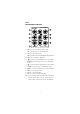
FUNCTIONAL DESCRIPTION HI 122 Front Panel Paper Roll Electrode Condition Primary LCD Secondary LCD Electrode Response ON OFF HI 122 AutoHOLD Print pH / mV Meter Paper CAL CFM CLR AutoLOG pH mV RelmV Reso NUM LOG Calibration Check 2 4 1 3 Rear Panel PIN pH/ORP 5 POWER 7 6 1) 2) 3) 4) 5) 6) 7) 8) 9) 10) TEMP RS232 9 8 10 Left Keyboard ON switch OFF switch Right Keyboard Pin input socket BNC electrode connector Temperature probe socket Power adapter socket RS232 serial communic
HI 120 KEYBOARD ON THE LEFT 1 3 2 AutoHOLD GLP SET 6 4 AutoLOG 9 5 7 pH mV RelmV Resolution 10 11 8 NUM 12 Shortcuts to alternate functions 1) AutoHOLD key, to freeze the first stable reading on the LCD. 2) GLP key, to display Good Laboratory Practice Information. 3) SET key, to enter/exit SETUP mode.
HI 120 MAIN KEYBOARD ON THE RIGHT HI 120 pH / mV Meter 3 1 2 CAL CFM CLR 5 6 4 MODE 7 9 8 LOG RCL Calibration Check 1) CAL key, to enter and exit/escape calibration mode. SET key (second function), to enter/exit SETUP mode. 2) CFM key, to confirm different values. GLP key (second function), to display Good Laboratory Practice Information. 3) CLR key, to clear calibration or logged data. 4) key, to manually increase temperature value or other parameters.
HI 122 KEYBOARD ON THE LEFT 1 3 2 AutoHOLD Print Paper 6 4 AutoLOG 9 5 7 pH mV RelmV Resolution 10 11 8 NUM 12 Shortcuts to alternate functions 1) AutoHOLD key, to freeze the first stable reading on the LCD. 2) Print key, to obtain a printout or to cancel printing. 3) Paper key, to pull out the paper.
HI 122 MAIN KEYBOARD ON THE RIGHT HI 122 pH / mV Meter 3 1 2 CAL CFM CLR 5 6 4 7 9 8 LOG Calibration Check 1) CAL key, to enter and exit/escape calibration mode. SET key (second function), to enter/exit SETUP mode. 2) CFM key, to confirm different values. GLP key (second function), to display Good Laboratory Practice Information. 3) CLR key, to clear calibration or logged data. 4) key, to manually increase temperature value or other parameters.
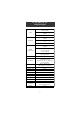
HI 120 AND HI 122 SPECIFICATIONS –2.00 to 16.00 pH –2.000 to 16.000 pH ±999.9 mV ±2000 mV RANGE –20.0 to 120.0 ºC (–4.0 to 248.0 ºF) 0.01 pH 0.001 pH 0.1 mV 1 mV RE SOLUTION 0.1 ºC (0.1 ºF) ±0.01 pH ±0.002 pH ACCURACY @ 20°C / 68°F ±0.2 mV (±699.9 mV) ±0.5 mV (±999.9 mV) ±1 mV (± 2000 mV) ±0.4 ºC (±0.7 ºF) (excluding probe error) Relative mV offset range ±2000 mV pH Calibration Up to five-point calibration, 7 standard buffers available (1.68, 4.01, 6.86, 7.01, 9.18, 10.01, 12.
OPERATIONAL GUIDE POWER CONNECTION Plug the 12 VDC adapter into the power supply socket. Notes: • These instruments use non volatile memory to retain the pH, mV, temperature calibrations and all other settings, even when unplugged. • Make sure a fuse protects the main line.
pH MEASUREMENTS Make sure the instrument has been calibrated before taking pH measurements. • Press MODE to enter pH mode. Note: To change pH resolution, press MODE again or simply Resolution from the left keyboard. • Submerge the electrode tip and the temperature probe approximately 4 cm (1½”) into the sample to be tested. Allow time for the electrode to stabilize. • The pH is displayed on the primary LCD and the temperature on the secondary LCD.
Press NUM to change the temperature value with the numerical keys. The “2nd” tag will blink. Press CLR if you want to delete digits of the displayed value. The remaining digits will shift to right. Introduce the desired value. If the value is out of temperature range, a long beep will be heard. Press NUM to confirm the new value or CAL to escape without changing the temperature.
The Relative mV reading is equal to the difference between the absolute mV input value and relative mV offset established in the relative mV calibration. TEMPERATURE MEASUREMENTS Connect the HI 7662-T temperature probe to the appropriate socket. Immerse the temperature probe into the sample and allow the reading on the secondary LCD to stabilize. Note: The temperature can be displayed in Celsius degrees (ºC) or in Fahrenheit degrees (ºF) (see SETUP for details, page 27).
pH CALIBRATION Calibrate the instrument often, especially if high accuracy is required. The instrument should be recalibrated: • Whenever the pH electrode is replaced. • At least once a week. • After testing aggressive chemicals. • If “CAL DUE” tags are blinking during measurement. • If “OUT CAL RANGE” message blinks during pH measurement (the measurement range is not covered by current calibration). PREPARATION Pour small quantities of the buffer solutions into clean beakers.
All new calibrations will override existing stored calibration data, in a ±0.2 pH window, at these calibration points. The slopes adjacent to the calibration points will be reevaluated. If the new calibration point has no correspondence in the existing stored calibration data, it is added to it if this is not full, or the instrument will ask which buffer will be replaced by the current buffer.
• The “ ” tag will blink on the LCD until the reading is stable. • When the reading is stable and close to the selected buffer, “CFM” tag blinks. • Press CFM to confirm calibration. • The calibrated value is then displayed on the primary CFM LCD and the secondary LCD will display the second expected buffer value, together with “CAL”, “Cal Point 2” and “7.01” tags and the corresponding buffer tag blinking.
• After the third calibration point is confirmed, immerse the pH electrode and the temperature probe approximately 4 cm (1½”) into the fourth buffer solution and stir gently. The temperature probe should be close to the pH electrode. • If necessary, press the ARROW keys to select a different buffer value. • The “ ” tag will blink on the LCD until the reading is stable. • When the reading is stable and close to the selected buffer, “CFM” tag blinks. • Press CFM to confirm calibration.
If the existing stored calibration is full (five calibration points), the instrument asks which buffer will be replaced by current buffer. Press the ARROW keys to select another buffer to be replaced. Press CFM to confirm the buffer that will be replaced. Press CAL to leave calibration without replacing. Note: The replaced buffer is not removed from calibration list and it can be selected for the next calibration points.
ENHANCED CALIBRATION MESSAGES The stored calibration history to used issue error and warning messages during calibration to help ensure the highest accuracy. As electrode aging is normally a slow process, substantial changes from previous calibrations are likely due to a temporary problem with the electrode or buffers. Calibrating under these conditions will result measurement errors. ERROR MESSAGES Error messages appear if one or all of the calibration parameters are out of accepted windows.
CLEAN ELECTRODE This warning message appears in order to alert the user that some dirt or deposits could be on the electrode. Refer to the electrode Cleaning Procedure. This ensures the removal of film, dirt or deposits on the glass bulb and reference junction. CONTAMINATED BUFFER This warning message appears in order to alert that the buffer could be contaminated. Refresh your buffer and continue the calibration procedure.
The electrode response is evaluated only when calibration has been performed using pH 7.01 or pH 6.86, pH 4.01 and pH 10.01 or pH 9.18 buffers. When the instrument cannot evaluate the electrode response or pH 1.68/12.45 buffer was used as calibration buffer, the response gauge will be empty. If the electrode is in a very poor condition, the first condition segment will blink. If the electrode response is very slow, the first response segment will blink.
GOOD LABORATORY PRACTICE (GLP) GLP is a set of functions that allows storage and retrival of data regarding the maintenance and status of the electrode. All data regarding pH and Rel mV calibration is stored for the user to review when necessary. CALIBRATION ALARM TIME OUT For pH calibration, all the instruments allow the user to set the number of days before the next required pH calibration. This value can be set from 1 to 7 days. The default setting is OFF (disabled).
• The pH calibration offset. • The pH calibration slope (the GLP slope is the average of the calibration slopes; the percentage is referred to the ideal value of 59.16 mV/pH). • The calibration buffers in calibrating order, with the corresponding warnings.
The fourth pH calibration buffer: The fifth pH calibration buffer: Notes: • The “OLd” message displayed beside the pH value means that this buffer was not used during last calibration. Press 2nd then SET key if you want to see calibration date (or time, if old calibration was performed in the same day with current calibration). • Each calibration buffer is displayed with the resolution from calibration moment.
LAST RELATIVE mV CALIBRATION DATA Last Relative mV calibration data is stored automatically after a successful calibration. To view the Relative mV calibration data, press 2nd then GLP key or simply GLP from the left keyboard (HI 120) while in Relative mV measurement mode. The instrument will display the Relative mV GLP information. • The date (yyyy.mm.dd) of the last calibration as in pH GLP mode.
SETUP Setup mode allows viewing and modifying the following parameters: • Calibration Alarm Time Out • One-point calibration behaviour • Custom Buffer 1 • Custom Buffer 2 • Alarm High Limit • Alarm Low Limit • AutoLOG Start Condition • AutoLOG End Condition • AutoLOG Interval • Temperature Unit • Current Date (yyyy.mm.
If there is another item to be set (e.g. minutes), press MODE or from the left keyboard. The other item will start blinking. / Press the ARROW keys to change the displayed value or simply use the numerical keys for all numerical parameters. Press CFM to confirm or CAL to escape. Press the ARROW keys to select the next/previous parameter. Press 2nd then SET key, or simply SET from the left keyboard (HI 120 only) to exit SETUP menu at any time. The instrument asks for printing a Setup Report (HI 122 only).
Notes: • The custom buffers can be set only with 0.001 pH resolution. If 0.01 pH resolution is selected during calibration, the displayed custom buffer value is a rounded one. • For calibration alarm time out, custom buffers, alarm limits, start and stop condition items, if pressing CLR while in changing mode, the selected item will be set to default. • Printer status and printing language items appear only for HI 122.
AutoLOG SETUP AutoLOG Start Condition • Select the “Strt” item. The displayed AutoLOG start condition will be the previous set one. The default value is “btn” – button (start with key). • Press and keep hold down MODE while in view mode, when time is displayed, to view the set date. • If pressing CAL while in view mode, the start time will be displayed. Notes: • Pressing CLR while in changing mode, the start condition will be set to default (“btn”).
LOGGING This feature allows the user to log pH and Rel mV, together with temperature automatically. All logged data can be transferred to a PC through the RS232 port. The maximum logging space is 1000 record locations (samples). This can be divided in 1 up to 50 lots (one lot can use all the free space). The lot ID (number) is between 1 and 99 (after 99 it restarts from 1). Only up to 50 lots can be memorized at one time, even if there is free space available.
If the LOG space is full, “FULL LOC” message will be displayed on the LCD for a few seconds with “LOG” tag blinking, and then ”FrEE 0” message. The instrument returns to normal measurement mode. AutoLOGGING The setable AutoLOG modes make these instruments very useful in a wide range of applications: • Start at button or set time/date; stop after a set duration. • Start at button or set time/date; stop when a set value is reached. • Start at button or set time/date; stop when a set sample number is reached.
To stop autologging, press 2nd then AutoLOG key again, or simply TEMPERATURE CALIBRATION AutoLOG from the left keyboard. (for technical personnel only) The instrument will display for a few seconds the lot number on the primary LCD and the sample number on the secondary LCD, together with “AutoLOG” tag, and will return to measurement mode. Notes: • If printer is ON, each logged sample is printed only if the AutoLOG interval is at least 30 s (HI 122 only).
Press MODE or from the left keyboard and the instrument will display the next logged parameter as shown in the table below: Parameter Primary LCD Secondary LCD mV mV reading Temperature TIME Hour & minutes Seconds DATE Year Month & day OFFSET Offset value Lot (or record) number SLOPE Slope value Lot (or record) number Notes: • If pressing from the left keyboard, the previous logged parameter will be displayed.
AutoHOLD To freeze the first stable reading on the LCD press 2nd then AutoHOLD key, or simply AutoHOLD from the left keyboard while the instrument is in measurement mode. The “Auto” ”HOLD” tags will be displayed blinking on the LCD until the reading will stabilize. When the reading is stable, the “Auto” “HOLD” tags stop blinking and the reading is frozen. Press 2nd then AutoHOLD key again, or simply AutoHOLD from the left keyboard to return to normal measurement mode.
PRINTING (HI 122 only) A complete set of information based on the measured, set or recorded data can be printed. Data can be printed on demand (for current reading in measurement mode, GLP and SETUP modes) by pressing 2nd then Print key, or simply Print from the left keyboard, or automatic (for AutoLOG and Log on demand modes). Automatic data printing is possible in AutoLOG mode only if the printer is ON and the AutoLOG interval is greater than 30 seconds.
When in SETUP mode, the following information can be printed: • If 2nd then Print key are the first INSTRUMENT SETUP keys pressed after entering SETUP Calibration Alarm Time Out mode, a SETUP table of contents One-point cal will be printed: behaviour pH Custom Buf.1 pH Custom Buf.2 Beep Alarms: Alarm high Alarm low AutoLOG: Start condition End condition Interval Current Date Current Time Printing Language Printer ON/OFF Beep ON/OFF Baud rate Command prefix Instrument ID Active Keys: -next item -prev.
• Press CFM to print the SETUP REPORT or CAL to escape without printing. When in SETUP mode, if pressing CAL, then Print for a chosen parameter, a help printout will come out, providing the following information (e.g. AutoLOG Interval): SETUP REPORT Instr ID 0002 Cal Time Out OFF One-Cal Point Pnt Custom Buffer Cb1 3.
• For AutoLOG mode: START AUTOLOG Instr ID 0002 Lot L03 Date 2004/10/15 Time 18:05:01 Interval 00:30 Slope 99.7% Offset 0.1mV Sample No pH mV °C 1 7.02 -0.5 25.0 Sample No pH mV °C 2 7.01 -0.2 25.0 Sample No pH mV °C 3 6.97 1.9 24.9 STOP AUTOLOG Date 2004/10/15 Time 18:06:51 Note: If selecting a different printing language, all data will be print in the selected language.
TEMPERATURE CALIBRATION (f o r t e c h n i c a l p e r s o n n e l o n l y ) All the instruments are factory calibrated for temperature. Hanna’s temperature probes are interchangeable and no temperature calibration is needed when they are replaced. If the temperature measurements are inaccurate, temperature recalibration should be performed. For an accurate recalibration, contact your dealer or the nearest Hanna Customer Service Center, or follow the instructions below.
• Press CFM to confirm. The instrument returns to measurement mode. Note: If the reading is not close to the selected calibration point, “WRONG” tag will blink. Change the temperature probe and restart calibration. CFM mV CALIBRATION (for technical personnel only) All the instruments are factory calibrated for mV. Hanna’s ORP electrodes are interchangeable and no mV calibration is needed when they are replaced. If the measurements are inaccurate, mV recalibration should be performed.
PC INTERFACE Data transmission from the instrument to the PC can be done with the HI 92000 Windows® compatible software (optional). HI 92000 also offers graphing and on-line help feature. Data can be exported to the most popular spreadsheet programs for further analysis. To connect your instrument to a PC, use the optional Hanna HI 920010 cable connector. Make sure that your instrument is switched off and plug one connector to the instrument RS232C socket and the other to the serial port of your PC.
CHR xx Change the instrument range according with the parameter value (xx): • xx=00 pH range/0.001 resolution • xx=01 pH range/0.
pH BUFFER TEMPERATURE DEPENDENCE Temperature has an effect on pH. The calibration buffer solutions are affected by temperature changes to a lesser degree than normal solutions. During calibration the instrument will automatically calibrate to the pH value corresponding to the measured or set temperature. TEMP pH BUFFERS ºC ºF 1.679 4.010 6.862 7.010 9.177 10.010 12.454 0 32 1.670 4.007 6.982 7.130 9.459 10.316 13.379 5 41 1.670 4.002 6.949 7.098 9.391 10.245 13.178 10 50 1.671 4.
ELECTRODE CONDITIONING & MAINTENANCE PREPARATION PROCEDURE Remove the protective cap of the pH electrode. DO NOT BE ALARMED IF SALT DEPOSITS ARE PRESENT. This is normal with electrodes. They will disappear when rinsed with water. During transport, tiny bubbles of air may form inside the glass bulb affecting proper functioning of the electrode. These bubbles can be removed by “shaking down” the electrode as you would do with a glass thermometer.
For refillable electrodes: If the filling solution (electrolyte) is more than 2½ cm (1”) below the fill hole, add HI 7082 or HI 8082 3.5M KCl Electrolyte Solution for double junction or HI 7071 or HI 8071 3.5M KCl+AgCl Electrolyte Solution for single junction electrodes. For faster response, unscrew the fill hole screw during measurements. For AmpHel® electrodes: If the electrode does not respond to pH changes, the battery run down and the electrode should be replaced.
pH CLEANING PROCEDURE • General Soak in Hanna HI 7061 or HI 8061 General Cleaning Solution for approximately ½ hour. • Protein Soak in Hanna HI 7073 or HI 8073 Protein Cleaning Solution for 15 minutes. • Inorganic Soak in Hanna HI 7074 Inorganic Cleaning Solution for 15 minutes. • Oil/grease Rinse with Hanna HI 7077 or HI 8077 Oil and Fat Cleaning Solution.
PRINTER MAINTENANCE (HI 122 only) HI 122 instrument uses plain paper rolls 44 mm width. To insert a new paper roll, follow the procedure below: • For an easier insertion, cut the paper edge as shown in the next figure: CUT • Put the paper roll on the paper holder attached to the printer. • Insert the paper edge into the printer slot as shown below: INSERT • Simply press Paper from the left keyboard to feed the printer. Allow about 5 cm (2”) to exit from the printer.
TROUBLESHOOTING GUIDE SYMPTOMS Slow response/excessive drift. PROBLEM D irty pH electrode. Readings fluctuate up Clogged/dirty junction. and down (noise). Low electrolyte level (refillable electrodes only). The display shows blinking dashes during pH measurements. SOLUTION Soak the electrode tip in HI 7061 solution for 30 minutes and then clean the electrode. Clean the electrode. Refill with fresh solution (for refillable electrodes only). Out of range in the pH Make sure the pH scale.
TROUBLESHOOTING GUIDE (cont.) SYMPTOMS PROBLEM SOLUTION The meter displays empty E lectrode Response scale. Not enough data available to evaluate the response time. Repeat calibration more carefully. At startup the meter displays all LCD permanently. One of the keys is blocked. Check the keyboard or contact the vendor. Long beep heard Key without function in D on't press keys without function in current mode. when pressing a key. current mode. E nd of range reached with the ARROW keys.
TEMPERATURE CORRELATION FOR pH SENSITIVE GLASS The resistance of glass electrodes partially depends on the temperature. The lower the temperature, the higher the resistance. It takes more time for the reading to stabilize if the resistance is higher. In addition, the response time will suffer to a greater degree at temperatures below 25 ºC (77 ºF). Since the resistance of the pH electrode is in the range of 50 – 200 Mohm, the current across the membrane is in the pico Ampere range.
ACCESSORIES pH BUFFER SOLUTIONS HI 70004P pH 4.01 Buffer Sachets, 20 mL, 25 pcs HI 70007P pH 7.01 Buffer Sachets, 20 mL, 25 pcs HI 70010P pH 10.01 Buffer Sachets, 20 mL, 25 pcs HI 7001L pH 1.68 Buffer Solution, 500 mL bottle HI 7004L pH 4.01 Buffer Solution, 500 mL bottle HI 7006L pH 6.86 Buffer Solution, 500 mL bottle HI 7007L pH 7.01 Buffer Solution, 500 mL bottle HI 7009L pH 9.18 Buffer Solution, 500 mL bottle HI 7010L pH 10.01 Buffer Solution, 500 mL bottle HI 7001L pH 1.
ORP PRETREATMENT SOLUTIONS HI 7091L Reducing Pretreatment Solution, 460 mL bottle HI 7092L Oxidizing Pretreatment Solution, 460 mL bottle pH ELECTRODES All electrodes with code ending with P are supplied with BNC & pin connectors and 1 m (3.3') cable, as shown below: HI 1043P Glass-body, double junction, refillable, combination pH electrode. Use: strong acid/alkali. HI 1053P Glass-body, triple ceramic, conic shape, refillable, combination pH electrode. Use: emulsions.
HI 1330P Glass-body, semimicro, single junction, refillable, combination pH electrode. Use: laboratory, vials. HI 1332P Plastic-body (Ultem®), double junction, refillable, combination pH electrode. Use: general purpose. ORP ELECTRODES HI 3131P Glass-body, refillable, combination platinum ORP electrode. Use: titration. Consult the Hanna General Catalog for more electrodes with BNC and pin connectors.
RECOMMENDATIONS FOR USERS Before using these products, make sure they are entirely suitable for the environment in which they are used. Operation of these instruments in residential areas could cause unacceptable interferences to radio and TV equipment, requiring the operator to follow all necessary steps to correct interferences. The glass bulb at the end of the pH electrode is sensitive to electrostatic discharges. Avoid touching this glass bulb at all times.
SALES AND TECHNICAL SERVICE CONTACTS Australia: Tel. (03) 9769.0666 • Fax (03) 9769.0699 China: Tel. (10) 88570068 • Fax (10) 88570060 Egypt: Tel. & Fax (02) 2758.683 Germany: Tel. (07851) 9129-0 • Fax (07851) 9129-99 Greece: Tel. (210) 823.5192 • Fax (210) 884.0210 Indonesia: Tel. (21) 4584.2941 • Fax (21) 4584.2942 Japan: Tel. (03) 3258.9565 • Fax (03) 3258.9567 Korea: Tel. (02) 2278.5147 • Fax (02) 2264.1729 Malaysia: Tel. (603) 5638.9940 • Fax (603) 5638.9829 Singapore: Tel. 6296.