HI 504910 Digital Transmitter Instruction Manual
TABLE OF CONTENTS WARRANTY . . . . . . . . . . . . . . . . . . . . . . . . . . . . . . 4 PRELIMINARY EXAMINATION . . . . . . . . . . . . . . . . . . 5 GENERAL DESCRIPTION . . . . . . . . . . . . . . . . . . . . . 5 FUNCTIONAL DESCRIPTION . . . . . . . . . . . . . . . . . . 6 SPECIFICATIONS . . . . . . . . . . . . . . . . . . . . . . . . . . . 9 INSTALLATION . . . . . . . . . . . . . . . . . . . . . . . . . . . 10 CALIBRATION MODE . . . . . . . . . . . . . . . . . . . . . . 12 SETUP MODE . . . . . . . . . .
Dear Customer, Thank you for choosing a Hanna Product. Please read this instruction manual carefully before using the instrument. It will provide you with the necessary information for correct use of the instrument, as well as a precise idea of its versatility. If you need additional technical information, do not hesitate to e-mail us at tech@hannainst.com.
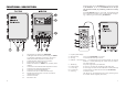
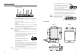
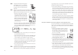
Keyboard and LCD for HI 504910 are normally provided by HI 504920. To do this, HI 504920 has to be put into terminal mode, by selecting code 90 in Setup mode. If the HI 504920 meter is not handy, the keyboard and LCD inside the transmitter case can be used for configuring, calibrating and monitoring HI 504910. FUNCTIONAL DESCRIPTION 1. 2. 3. 4. 5. 6. 7. 8. 9. 10. 11. 12.
Note Throughout this manual every reference to keyboard or LCD refers to HI 504920 keyboard and LCD. SPECIFICATIONS Range -2.00 to 16.00 pH -2000 to 2000 mV -30 to 130.0 ºC Resolution 0.01 pH 1 mV 0.1 ºC Accuracy ±0.02 pH ±2 mV ±0.5 ºC When using the HI 504910 internal keyboard and LCD, refer to the below table to match keys. HI 504920 HI 504910 DISPLAY DISPLAY (ALT+) CAL DATA CAL DATA (ALT+) SETUP æ SETUP æ (ALT+) CAL (@20°C/68°F) Typical EMC Deviation CAL ±0.2 pH ±10 mV ±0.
• pH or ORP electrode: connect the shield of the electrode coaxial cable (electrode reference) to the terminal #10, and the electrode coaxial cable core to terminal #11. To benefit from the differential (symmetrical) input, connect the proper electrode wire or a cable with a potential matching pin (grounding bar) to the relevant terminal (#9). If the matching pin is not available, short pins #9 and #10. INSTALLATION • Remove the connectors protecting shield and wire the meter as explained below.
CALIBRATION MODE The calibration mode allows to calibrate the pH/ORP and temperature inputs. The instrument is factory calibrated for all these parameters. Periodical calibration of the instrument is recommended, in particular when greatest accuracy is required and at least biyearly. The electrode can be calibrated over only one point but, when possible, it is always good practice to perform a 2point calibration.
HI 504920 pH reading. Both pH tags blink alternatively. • To return to normal mode, press ALT and TXCAL. • If a communication error between the portable meter and the transmitter occurs, the primary LCD shows the “rSEr” message: check the interface cable and connections. • If the LCD shows “...”, verify that the HI 504910 transmitter be configured for pH (not for ORP) measurement.
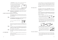
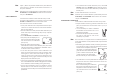
Note Note The electrode should be submerged approximately 4 cm (11/2’’) in the solution. The temperature probe has to be located as close as possible to the pH electrode. When it is not possible to immerse the Potential Matching Pin together with the pH electrode in the solution, disable the differential input by setting setup item I.04 to “OFF”.
Note If (ALT+) SETUP are pressed instead of CFM, the calibration value selection is aborted and the meter reverts back to a two-point calibration. Note Whenever a pH or ORP calibration is performed by means of HI 504920, the HI 504920 date and time are automatically set in HI 504910. ORP CALIBRATION Check that the code 90 has been entered in Setup mode. To perform ORP calibration it is necessary to connect an HI 931001 or HI 8427 simulator to the BNC socket. The meter has to be set as ORP controller.
• When the reading becomes stable, if the temperature value is close to the calibration point the CFM tag starts blinking, otherwise the WRONG indicator will flash. • In the first case press the CFM key to confirm calibration. The meter will proceed showing the scrolling message “Press CFM again to confirm the current buffer or right to escape” (to prevent from confirming the calibration point inadvertently). • Pressing again the CFM key, the secondary LCD will display the second calibration point.
Note SETUP MODE The Setup Mode allows the user to set all needed characteristics of the meter. Press (ALT+) SETUP and enter the password when the device is in idle or control mode. If the correct password is not entered, the user can only view the setup parameters (except for passwords) without modifying them (and the device continues to acquire and transmit measurements).
Code Valid Values Default Present for ORP G.00 pH/ORP input “PH”, “OrP” (see note 4) “PH” yes G.01 Temperature compensation “AtC”: Automatic “USEr”: Manual (see note 3) “AtC” no G.02 Manual or probe error temperature -30 to 130.0 ºC (see note 3) 25.0 no G.10 Factory ID 0000 to 9999 (see note 9) 0000 yes G.11 Instrument ID alias RS485 address 00 to 99 (see note 9) 00 yes G.98 Calibration password 0000 to 9999 (see notes 1, 9) 0000 yes G.
Code Valid Values Default Present for ORP CELLULAR/MODEM/PC CONNECTION (“PHOn”) P.00 RS485 connection type (see note 9) “PC”=PC or modem connection “PC” “CELL”=cellular module connection yes P.01 PIN number (see note 9) 0000 to 9999 0000 yes F.00 pH or ORP actual value (see note 7) measured value -1.00 pH or -200 mV to measured value +1.00 pH or +200 mV measured value yes F.01 pH or ORP reading offset adjustment -1.00 to +1.00 pH or -200 to +200 mV 0.00 pH or 0 mV yes F.
MEASURE MODE • The measure mode is the normal mode for the instrument. During measure mode, pH and temperature or ORP measurements are acquired and sent to HI 504 or to a PC with HI 92500 or another software implementing the communication protocol described in this manual (see the “RS485 communication section”). In a normal situation, during measure mode the green LED is ON and the red LED is OFF (LEDs are located inside the instrument case).
pH/ORP PROBE CHECK Note Note 30 The pH electrode and the reference electrode for both pH and ORP can be automatically monitored through HI 504910. Setup items involved are I.13 (pH electrode impedance test enable), I.14 (reference electrode impedance test enable) and I.15 (maximum reference electrode impedance). A “pH electrode broken or leakage error” (error code: 10) is generated whenever the pH electrode impedance is less than 1 MΩ.
LAST CALIBRATION DATA If the instrument is set as pH meter, the following data about the last calibration are stored in the EEPROM: • Date • time • offset, in mV • slope, in mV/pH • up to two buffers. If the instrument is set as ORP meter, the data stored in the EEPROM are the following: • Date • time • first calibration point • second calibration point. While displaying these data the HI 504910 continues to acquire and transmit measurements. To enter the last calibration data mode, press (ALT+) CAL DATA.
• If an offset calibration has been made, the instrument will turn to “slope” calibration (as indicated by the “SLO” message on the secondary display. The slope value is shown on the primary LCD and the first digit is blinking to permit modifications). • Press the æ or key to modify the value or key to move to the next digit. • Once selected the desired value, press CFM to confirm. • After confirmation the instrument will turn back to normal mode.
If the event is an error still active, the error code on the primary LCD will blink, otherwise it will be fixed. To have a look at the additional information of a selected event press the key (it will cycle through the additional information). EVENT LOG FILE SCROLLING The event log file is composed of maximum 100 recorded events, which include errors, calibration events (type of calibration, date, time) and configuration changes.
FAULT CONDITIONS RS485 COMMUNICATION The below fault conditions may be detected by the software: • EEPROM data error • serial communication internal bus failure • dead loop. EEPROM data error can be detected through EEPROM test procedure at start-up or when explicitly requested using setup menu, or during normal operational mode if a checksum control fails. When an EEPROM error is detected during normal mode, a fault alarm is generated.
If using HI 504 the fail safe resistors are already connected on it, so they are necessary only if the HI 504910 transmitter is connected to a PC. The interface signals are optoisolated from the ground of the instrument, the electrode and the temperature sensor. Before connecting the meter to the computer, consult the computer manual. The instrument can only work as a slave component. In other words it can work as a remote terminal equipment answering to the commands only.
Following is the complete list of commands available: (*) C1C2C3C4 are ASCII chars corresponding to the setup item Command content; P1P2 are two additional bytes used for sign and half digit as follows: Remarks NNMDR not available NNSTS not available Requests instrument status (LEDs, configuration change flag, etc.
The “NNSET...” and “NNGET...” commands when used for password items, baud rate, F.00 and F.10 items, are answered with “NN”.
buf1 ASCII string for a float (example: “7.01”) buf2 ASCII string for a float (example: “4.01”) When some of the above items is missing (for example buf3 when a 2-point calibration is performed) it is indicated with a “N” letter.
Note Note 48 desAmdesBm” where m is the number of events. Each token is followed by a blank space, except the last one (“desBm”), directly followed by the character. “new_events_no” is the number of new events and its format is the ASCII format for a number (“1”, “2”.... “99”, “100”). When a NNEVF or NNEVN command is received by the instrument, the new events list is reset and a following NNEVN command will be answered with “NN0” if no event took place in the meantime.
MODEM CONNECTION Note Note Note Note 50 A momodem connection can be established between HI504910 and a remote computer over a telephone line. It is possible to make two different type of remote connection: • Over the GSM network, connecting the HI504900 cellular module to HI504910 RS485 port. To enable the modem connection with HI504900 first it is necessary to configure the cellular phone: set item P.01 with the PIN code of the SIM card in the HI504900 module and then set item P.00 to “CELL”.
When making a call, after the data connection is established, the “NNPWD...” command (where “NN” is the address of the device controlling the modem, i.e. the one with O.31 set to “On”) must be issued by the remote computer within 15 seconds. When the data connection is up, the RS485 protocol for a remote connection is all the same as for a local network (see the previous section). An automatic disconnection takes place if no character is received in the RS485 network in 3-4 minutes.
LEDs TEST EEPROM SELFTEST The EEPROM selftest procedure involves verifying the stored EEPROM checksum. • To enter the EEPROM test procedure select the setup item t.02 and an “OFF” blinking message will appear on the LCD. • Press the æ (or ) key once and the message will switch to a blinking “GO”. • Press CFM key to confirm or the æ (or ) key again to return to the previous status.
pH VALUES AT VARIOUS TEMPERATURES Temperature has a significant effect on pH. The calibration buffer solutions are effected by temperature changes to a lesser degree than normal solutions. For manual temperature calibration please refer to the following chart: TEMP °C °F 32 0 41 5 10 50 15 59 20 68 25 77 30 86 35 95 40 104 45 113 50 122 55 131 60 140 65 149 70 158 4.01 4.01 4.00 4.00 4.00 4.00 4.01 4.02 4.03 4.04 4.05 4.06 4.07 4.09 4.11 4.12 6.86 6.98 6.95 6.92 6.90 6.88 6.86 6.85 6.84 6.84 6.83 6.83 6.
- Make sure cable and connections are not damaged nor lying in a pool of water or solution. • Slow Response/Excessive Drift: soak the tip in Hanna Solution HI 7061 for 30 minutes, rinse thoroughly in distilled water and then follow the Cleaning Procedure above. • For ORP Electrodes: polish the metal tip with a lightly abrasive paper (paying attention not to scratch the surface) and wash thoroughly with water. PERIODIC MAINTENANCE Inspect the electrode and the cable.
ACCESSORIES pH CALIBRATION SOLUTIONS HI 7611 HI 7004M or HI 7004L HI 7006M or HI 7006L HI 7007M or HI 7007L HI 7009M or HI 7009L HI 7010M or HI 7010L HI 7621 pH 4.01 Buffer Solution, 230 or 500 ml bottle pH 6.86 Buffer Solution, 230 or 500 ml bottle pH 7.01 Buffer Solution, 230 or 500 ml bottle pH 9.18 Buffer Solution, 230 or 500 ml bottle pH 10.
pH AND ORP ELECTRODE HOLDERS HI 60542 In-line electrode holder for direct pipe installation HI 60545 Bypass loop electrode holder HI 60501 Specifications HI 60542 HI 60545 HI 60501 Electrode Holder Material PVC PVC PVC O-Ring Material NBR NBR NBR Min. & Max. Temperature 62 Immersion electrode holder for tanks, vessels, baths and open channels -10°C (14°F) & 60°C (144°F) Min. Immersion Length Max. Immersion Length --- --- 10 cm (3.9’’) 69 cm (27.1’’) Max.
pH AND ORP ELECTRODES CE DECLARATION OF CONFORMITY Hanna Instruments produces a wide range of pH and ORP electrodes specifically designed for needs of industrial uses. For a complete list of available electrodes visit our web site at www.hannainst.com or contact your dealer.
USER NOTES 66 67
TECHNICAL SERVICE CONTACTS Australia: Tel. (03) 9769.0666 • Fax (03) 9769.0699 China: Tel. (10) 88570068 • Fax (10) 88570060 Egypt: Tel. & Fax (02) 2758.683 Germany: Tel. (07851) 9129-0 • Fax (07851) 9129-99 Greece: Tel. (210) 823.5192 • Fax (210) 884.0210 Indonesia: Tel. (21) 4584.2941 • Fax (21) 4584.2942 Japan: Tel. (03) 3258.9565 • Fax (03) 3258.9567 Korea: Tel. (02) 2278.5147 • Fax (02) 2264.1729 Malaysia: Tel. (603) 5638.9940 • Fax (603) 5638.9829 Singapore: Tel. 6296.7118 • Fax 6291.