
User Guide


3534
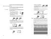
• Use the ! or " to make the
HI 931002 or multimeter out-
put correspond with the meter’s
value shown on the second-
ary display (e.g. 4).
• Wait for approximately 30 seconds (until the reading of the
calibrator is stable).
• Press CFM to confirm. The meter will switch to the second
calibration point. Repeat the above procedure.
• After the desired readings are obtained, press CFM and
the meter will skip back to normal operational mode.
Note When adjusting values using the ! or " keys it is important
to allow for sufficient response time (up to 30 seconds)
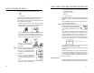
The table below lists the values of output codes along with
the calibration point values (which are the analog output
minimum and the analog output maximum) as indicated on
the display.
The secondary display indicates the current calibration point
value, while primary display indicates the current calibration
type.
OUTPUT CALIBRATION CALIBRATION CALIBRATION
TYPE CODE POINT 1 POINT 2
0-1 mA 0 0 mA 1 mA
0-20 mA 1 0 mA 20 mA
4-20 mA 2 4 mA 20 mA
0-5 VDC 3 0 VDC 5 VDC
1-5 VDC 4 1 VDC 5 VDC
0-10 VDC 5 0 VDC 10 VDC
way, or if the controller is switched off before the last step, no
calibration data is stored in non-volatile memory (EEPROM).
ANALOG OUTPUT CALIBRATION
In the meters where the analog output is available, this fea-
ture is factory calibrated through software. The user may also
perform these calibration procedures.
IMPORTANT It is recommended to perform the output calibration at least
once a year. Calibration should only be performed after 10
minutes from power up.
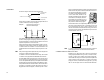
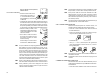
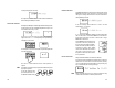
• With a multimeter or an HI 931002
connect the common port to the
ground output and the second port
to the current output or voltage out-
put (depending on which parameter
is being calibrated).
• Press and hold in sequence CFM first, then # and then
CAL to enter the Analog Output Calibration mode.
• Execute the password procedure.
• The primary display will show the current selected param-
eter blinking. Use the ! to select the code (0-5 see chart
below) for the desired parameter displayed on the second-
ary display (e.g. 4-20 mA).
• Press CFM to confirm the selected parameter that will stop
blinking on the primary display. The secondary display shows
the HI 931002 or multimeter input value as lower limit of
the interval.