
User Guide


2928
The user should select the appropriate range to calibrate (setup
code 03). Calibration must be performed for each range used.
The temperature probe should also be connected to the pro-
cess meter. The meters are equipped with a stability indicator.
The user is also guided with indications on the display during
the calibration procedure.
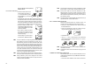
Initial Preparation
Pour a small quantity of the calibration solution (e.g. 1413 µS)
into a beaker. If possible, use a plastic beaker to minimize
any EMC interference.
For accurate calibration use two beakers containing the same
solution, the first one for rinsing the probe, the second one
for calibration. By doing this, contamination between the so-
lutions is minimized.
To obtain accurate readings, use the calibration solution in
the selected range and closer to the values to be measured.
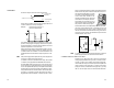
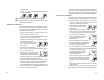
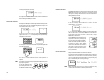
Offset Calibration
• To perform the EC or TDS calibra-
tion enter the calibration mode, by
pressing CAL and entering the pass-
word.
• After the correct password is en-
tered, the control actions stop and
the primary LCD will display the first
EC or TDS calibration value, with
the "CAL" indicator blinking. The sec-
ondary LCD displays the temperature.
Note If the wrong password is entered the system reverts back to
normal operation, displaying EC or TDS values.
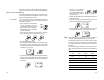
• 0 is the default value for the 1
st
calibration point. Dry the
conductivity probe and leave it in air.
• Only when the reading is stable the
"CAL" indicator will stop flashing (af-
ter about 30 seconds) and the
"READY" and "CFM" indicators will
start blinking.
• Press CFM to confirm the calibration
point; the primary LCD will display
the second expected buffer value.
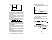
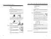
output matching a different EC or TDS range, for example,
4 mA = 30 mS and 20 mA = 50 mS.
To change the default values, the setup mode must be en-
tered. Setup codes for changing the analog output minimum
and maximum are 41 or 42, respectively. For the exact pro-
cedure, refer to the setup mode section in the manual.
Note The analog output is factory calibrated through software. The
user may also perform the calibration procedure as explained
in the following. It is recommended to perform the output
calibration at least once a year.
Note Analog output resolution is 1.5‰ f.s. with 0.5% f.s. accu-
racy.
Note The analog output is “frozen” when entering the setup or
calibration mode (after password confirmation).
CALIBRATION
The controller is factory calibrated for temperature as well as
for the analog input and outputs.
The user should periodically calibrate the instrument for EC
or TDS. For greatest accuracy, it is recommended that the
instrument is calibrated frequently.
Before beginning normal operation,it is recommended to stan-
dardize the probe with the Hanna calibration solution close
to the expected sample value and inside the selected range.
EC AND TDS CALIBRATION
The calibration points for EC and TDS are as follows:
Range Calibration point(s)
0.0÷199.9 µS 84.0 µS
0÷1999 µS 1413 µS
0.00÷19.99 mS 5.00 - 12.88 mS
0.0÷199.9 mS 80.0 - 111.8 mS
0.0÷100.0 ppm 42.0 ppm
0÷1000 ppm 800 ppm
0.00÷10.00 ppt 6.44 ppt
0.0÷100.0 ppt 55.9 ppt