
Product Manual


XR1 Datasheet
7
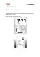
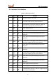
2.2 Interface Pin Definition
Table 2-1 XR1 interface pins
Pin No.
Symbol
I/O Type
Function
1
VIN
P
TXD1 level convertor,5V or 3.3V
2
TXD1
I/O
Serial interface transmission pin (UART_TX), which is
connected to PA17 (pin 39) on the internal IC
3
RXD1
I/O
Serial interface receiving pin (UART_RX), which is
connected to PA18 (pin 40) on the internal IC
4
VCC
P
Power input pin (3.3 V)
5
GND
P
Power supply reference ground pin
6
PA22
I/O
PA22, which is connected to PA22 (pin 44) on the
internal IC
7
PA21
I/O
PA21, which is connected to PA21 (pin 43) on the
internal IC
8
TXD0
I/O
Can be used as a debugging serial interface pin and is
connected to PB00 (pin 49) on the internal IC
9
PA12
I/O
PA12, which is connected to PA12 (pin 30) on the
internal IC
10
PA20
I/O
PA20, which is connected to PA20 (pin 42) on the
internal IC
11
RXD0
I/O
Can be used as a debugging serial interface pin and is
connected to PB01 (pin 48) on the internal IC
12
PA14
I/O
PA14, which is connected to PA14 (pin 32) on the
internal IC
13
PA19
I/O
PA19, which is connected to PA19 (pin 41) on the
internal IC
14
GND
P
Power supply reference ground pin
15
GND
P
Power supply reference ground pin
16
EN
I/O
Enable/Reset pin (This pin is active at a high level, and
is at a high level by default.)