
User's Manual


WR3LV1.0.0 User Manual
Version1.0.0
8
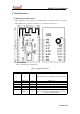
VD33
P
Module power supply pin (3.3 V)
9
GND
P
Power supply reference ground pin
10
ADC
AI
ADC port, with the maximum input voltage of 5 V
11
GPIOA_29
I/O
UART_Log_RXD (used for printing the internal
information of the module)
12
GPIOA_30
I/O
UART_Log_TXD (used for printing the internal
information of the module)
13
GPIOA_5
I/O
GPIOA_5, used for hardware PWM
14
GPIOA_12
I/O
GPIOA_12, used for hardware PWM
15
RXD
I/O
UART0_RXD (user’s serial port)
16
TXD
I/O
UART0_TXD (user’s serial port)
Note: P indicates power-supply pins, I/O indicates input/output pins, and AI indicates
analog input pins.
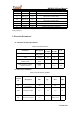
3. Electrical Parameters
3.1 Absolute electrical parameters
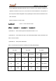
Table 3.1,Absolute Parameters
Parameters
Description
Minimu
m value
Maximu
m value
Unit
Ts
Storage
temperature
–40
125
°C
VDD
Power-supply
voltage
–0.3
3.6
V
Static electricity voltage
(human model)
TAMB –
25°C
-
2
kV
Static electricity voltage
(machine model)
TAMB –
25°C
-
0.5
kV
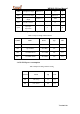
3.2 Electrical Conditions
Table 3.2 Normal electrical conditions
Paramet
ers
Description
Min
Typ
Max
Unit
Ta
Working
temperature
–20
-
105
°C
VDD
Working voltage
3.0
3.3
3.6
V
VIL
I/O low-level input
–0.3
-
VDD x 0.25
V