
User's Manual


WR3LV1.0.0 User Manual
Version1.0.0
2. Module Interfaces
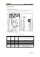
2.1 Dimensions and Pin Layout
WR3L provides two rows of pins (2 x 8) with the distance of 2 mm between every two pins.
WR3L dimensions: 16 mm (W) x 24 mm (L) x 3.3 mm (H) (see figure 2.1)
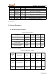
2.2 Pin definition
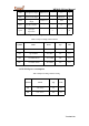
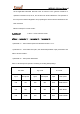
Table 2.1 describes the common pins.
Table 2.1,WR3L pins description
No. Symbol I/OType Function
1 NC / Disconnected to be compatible with other modules
2 GPIOA_22 I/O GPIOA_22
3 CHIP_EN I/O External enablement reset pin (valid at low level)
4 GPIOA_19 I/O GPIOA_19
5 GPIOA_14 I/O GPIOA_14, used for hardware PWM
6 GPIOA_15 I/O GPIOA_15, used for hardware PWM
7 GPIOA_0 I/O
GPIOA_0, which cannot be pulled up during
power-on and can be configured after power-on. It
is used for hardware PWM.