
Product Manual

WB3L Datasheet
Hangzhou Tuya Information Technology Co., Ltd. 7 V1.0.0
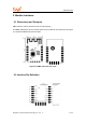
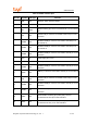
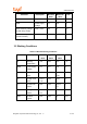
Table 2-1 WB3L interface pins
Pin No.
Symbol
I/O Type
Function
1 RST I/O Reset pin, which is disconnected
2 ADC AI ADC pin, which is connected to the P23 pin on the internal IC
3 EN Input
Module enabling pin, which is connected to 3.3 V for normal
use
4 P14 I/O
Common I/O pin, which is connected to the P14 pin on the
internal IC
5 PWM5 I/O
Hardware PWM pin, which is connected to the P26 pin on
the internal IC
6 PWM4 I/O
Hardware PWM pin, which is connected to the P24 pin on
the internal IC
7 PWM0 I/O
Hardware PWM pin, which is connected to the P6 pin on the
internal IC
8 VCC P Power supply pin (3.3 V)
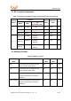
9 GND P Ground pin
10 PWM3 I/O
Hardware PWM pin, which is connected to the P9 pin on the
internal IC
11 TXD2 I/O
UART2_TX, which is connected to the P0 pin on the internal
IC
12 P16 I/O
Common I/O pin, which is connected to the P16 pin on the
internal IC
13 PWM2 I/O
Hardware PWM pin, which is connected to the P8 pin on the
internal IC
14 PWM1 I/O
Hardware PWM pin, which is connected to the P7 pin on the
internal IC
15 RXD1 I/O
Serial interface receiving pin (UART_RX), which is
connected to the P10 pin on the internal IC
16 TXD1 I/O
Serial interface transmission pin (UART_TX), which is
connected to the P11 pin on the internal IC