
Data Sheet


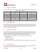
Table Of Contents
- 1.General Overview
- 1.1.Introduction
- 1.2.Features
- 1.3.Parameters
- 1.4.Ultra Low Power Technology
- 1.5.Major Applications
- 2.Hardware Overview
- 3.Pins and Definitions
- 3.1.GPIO
- 3.2.Secure Digital Input/Output Interface (SDIO)
- 3.3.Serial Peripheral Interface (SPI/HSPI)
- 3.4.Inter-integrated Circuit Interface (I2C)
- 3.5.I2S
- 3.6.Universal Asynchronous Receiver Transmitter (UART)
- 3.7.Pulse-Width Modulation (PWM)
- 3.8.IR Remote Control
- 3.9.ADC (Analog-to-digital Converter)
- 3.10.LED Light and Button
- 4.Firmware & Software Development Kit
- 5.Power Management
- 6.Clock Management
- 8.FCC Warming Statement
- This device complies with part 15 of the FCC Rules
- (1)This device may not cause harmful interference,
- (2)and this device must accept any interference re
- FCC Radiation Exposure Statement:
- This equipment complies with FCC radiation exposur
- Information to the user.
- Note: This equipment has been tested and found to
- -Reorient or relocate the receiving antenna.
- -Increase the separation between the equipment and
- -Connect the equipment into an outlet on a circuit
- -Consult the dealer or an experienced radio/TV tec
- 9.Appendix: QFN32 Package Size

ESP8266 Datasheet
Espressif Systems
Espressif Systems
June1,2015
23
/
32
(2)
If 18 =< vdd33_const =< 36, ESP8266EX RF Calibration and optimization process is
implemented via (vdd33_const/10).
(3)
If vdd33_const < 18 or 36 < vdd33_const < 255, ESP8266EX RF Calibration and optimization
process is implemented via the default value 3.0V.
Note Two:
Function
system_get_vdd33
is used to test the power supply voltage of VDD3P3 (Pin 3 and Pin 4).
Details on this function are described below:
(1) Pin Tout must be dangled. The 107th byte of esp_init_data_default.bin (0 - 127 byte),
“vdd33_const“, must set to be 0xFF.
(2) If the 107th byte of
esp_init_data_default.bin
(0 - 127 byte), “vdd33_const“, is equal to
0xff
, the returned value of function
system_get_vdd33
will be an effective value, otherwise
0xffff
will be returned.
(3)
The unit of the returned value is: 1/1024 V.
Note Three:
Function system_adc_read is defined to test the input voltage of Pin TOUT (Pin 6). Details on this
function are described below:
(1) The value of the 107th byte of esp_init_data_default.bin (0 - 127 byte), “vdd33_const“,
must be set to be the real power supply voltage of Pin 3 and Pin 4.
(2) If the 107th byte of
esp_init_data_default.bin
(0 - 127 byte), “vdd33_const“, is NOT
equal to
0xff
, the returned value of
system_adc_read
will be an effective value of the input voltage
of Pin TOUT, otherwise
0xffff
will be returned.
(3)
The unit of the returned value is: 1/1024 V.
3.10.
LEDLightandButton
ESP8266EX features up to 17 GPIOs, all of which can be assigned to realise various functions of LED
lights and buttons. Definitions of some GPIOs that are assigned with certain functions in our demo
application design are shownbelow:
Table 17 Pin Definitions of LED and Button
Pin Name
Pin Num
IO
Function Name
MTCK
12
IO13
Button (Reset)
GPIO0
15
IO0
WiFi Light
MTDI
10
IO12
Link Light