
Data Sheet


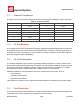
Table Of Contents
- 1.General Overview
- 1.1.Introduction
- 1.2.Features
- 1.3.Parameters
- 1.4.Ultra Low Power Technology
- 1.5.Major Applications
- 2.Hardware Overview
- 3.Pins and Definitions
- 3.1.GPIO
- 3.2.Secure Digital Input/Output Interface (SDIO)
- 3.3.Serial Peripheral Interface (SPI/HSPI)
- 3.4.Inter-integrated Circuit Interface (I2C)
- 3.5.I2S
- 3.6.Universal Asynchronous Receiver Transmitter (UART)
- 3.7.Pulse-Width Modulation (PWM)
- 3.8.IR Remote Control
- 3.9.ADC (Analog-to-digital Converter)
- 3.10.LED Light and Button
- 4.Firmware & Software Development Kit
- 5.Power Management
- 6.Clock Management
- 8.FCC Warming Statement
- This device complies with part 15 of the FCC Rules
- (1)This device may not cause harmful interference,
- (2)and this device must accept any interference re
- FCC Radiation Exposure Statement:
- This equipment complies with FCC radiation exposur
- Information to the user.
- Note: This equipment has been tested and found to
- -Reorient or relocate the receiving antenna.
- -Increase the separation between the equipment and
- -Connect the equipment into an outlet on a circuit
- -Consult the dealer or an experienced radio/TV tec
- 9.Appendix: QFN32 Package Size

ESP8266 Datasheet
Espressif Systems
Espressif Systems
June1,2015
22
/
32
The function used to test the input voltage of TOUT is: uint16 system_adc_read(void)
RF-init parameter in the following passage refers to esp_init_data_default.bin
Application One:
Test the power supply voltage of VDD3P3 (Pin 3 and Pin 4).
Hardware Design:
TOUT must be dangled.
RF-init Parameter: The 107th byte of
esp_init_data_default.bin
(0 - 127 byte),
“vdd33_const“, must set to be 0xFF, i.e., the value of “vdd33_const“ is 255.
RF Calibration
Process:
Optimize the RF circuit conditions based on the testing results of VDD3P3 (Pin 3
and Pin 4).
User Programming:
Use system_get_vdd33 instead of system_adc_read.
Application Two: Test the input voltage of TOUT (Pin6).
Hardware Design:
The input voltage range is 0 to 1.0 V when TOUT is connected to external
circuit.
RF-init Parameter: The value of the 107th byte of esp_init_data_default.bin (0 - 127
byte), “vdd33_const“, must be set to be the real power supply voltage of Pin
3 and Pin 4.
The working power voltage range of ESP8266EX is between 1.8V and 3.6V,
while the unit of “vdd33_const“ is 0.1V, therefore, the effective value range
of “vdd33_const“ is 18 to36.
RF Calibration
Process:
Optimize the RF circuit conditions based on the value of “vdd33_const“.
The permissible error is±0.2V.
User Programming:
Use
system_adc_read
instead of
system_get_vdd33
.
Note One:
In
RF_init
parameter
esp_init_data_default.bin
(0 - 127 byte), the 107th byte is defined as
“vdd33_const“. Definitions of “vdd33_const“ is described below:
(1)
If vdd33_const = 0xff, the power voltage of Pin 3 and Pin 4 will be tested by the internal self-
calibration process of ESP8266EX chipset itself. RF circuit conditions should be optimized according
to the testing results.