
Data Sheet

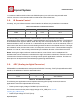


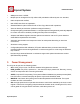


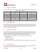
Table Of Contents
- 1.General Overview
- 1.1.Introduction
- 1.2.Features
- 1.3.Parameters
- 1.4.Ultra Low Power Technology
- 1.5.Major Applications
- 2.Hardware Overview
- 3.Pins and Definitions
- 3.1.GPIO
- 3.2.Secure Digital Input/Output Interface (SDIO)
- 3.3.Serial Peripheral Interface (SPI/HSPI)
- 3.4.Inter-integrated Circuit Interface (I2C)
- 3.5.I2S
- 3.6.Universal Asynchronous Receiver Transmitter (UART)
- 3.7.Pulse-Width Modulation (PWM)
- 3.8.IR Remote Control
- 3.9.ADC (Analog-to-digital Converter)
- 3.10.LED Light and Button
- 4.Firmware & Software Development Kit
- 5.Power Management
- 6.Clock Management
- 8.FCC Warming Statement
- This device complies with part 15 of the FCC Rules
- (1)This device may not cause harmful interference,
- (2)and this device must accept any interference re
- FCC Radiation Exposure Statement:
- This equipment complies with FCC radiation exposur
- Information to the user.
- Note: This equipment has been tested and found to
- -Reorient or relocate the receiving antenna.
- -Increase the separation between the equipment and
- -Connect the equipment into an outlet on a circuit
- -Consult the dealer or an experienced radio/TV tec
- 9.Appendix: QFN32 Package Size

ESP8266 Datasheet
Espressif Systems
Espressif Systems
June1,2015
21
/
32
i.e., between 100Hz and 1KHz. When the PWM frequency is at 1 KHz, the duty ratio will reach
1/22727, and over 14 bit resolution will be achieved at 1KHz refresh rate.
3.8.
IR Remote Control
Currently, only one Infrared remote control interface is defined, the pin definition is as below:
Table 14 Pin Definition of IR Remote Control
Pin Name
Pin Num
IO
Function Name
MTMS
9
IO12
IR Tx
GPIO5
24
IO5
IR Rx
The functionality of Infrared remote control interface can be implemented via software
programming. NEC coding, modulation, and demodulation are used by this interface. The frequency
of modulated carrier signal is 38KHz, while the duty ratio of the square wave is 1/3. The length of
data transmission, which is around 1m, is determined by two factors: one is the maximum value of
rated current, the other is internal current-limiting resistance value in the infrared receiver. The larger
the resistance value, the lower the current, so is the power, and vice versa. The transmission angle is
between 15° and 30°, and is mainly determined by the radiation direction of the infrared receiver.
Notes: Among the eight interfaces mentioned above, most of them can be multiplexed. Pin
definitions that can be defined is not limited to the eight ones herein mentioned, customers can self
customise the functions of the pins according to their specific application scenarios. Functions of
these pins can be implemented via software programming and hardware.
3.9.
ADC (Analog-to-digital Converter)
ESP8266EX is embedded with a 10-bit precision SARADC.Currently, TOUT(Pin6) is defined as ADC
interface, the definition of which is described below:
Pin Name
Pin Num
Function Name
TOUT
6
ADC Interface
Table 16 Pin Definition of ADC
The following two applications can be implemented using ADC (Pin6). However, these two
applications cannot be implementedconcurrently.
•
Test the power supply voltage of VDD3P3 (Pin 3 and Pin 4).
The function used to test the power supply voltage on PA_VDD pin is:
uint16
system_get_vdd33(void)
•
Test the input voltage of TOUT (Pin 6):