
Data Sheet
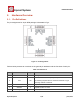


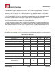


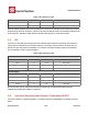
Table Of Contents
- 1.General Overview
- 1.1.Introduction
- 1.2.Features
- 1.3.Parameters
- 1.4.Ultra Low Power Technology
- 1.5.Major Applications
- 2.Hardware Overview
- 3.Pins and Definitions
- 3.1.GPIO
- 3.2.Secure Digital Input/Output Interface (SDIO)
- 3.3.Serial Peripheral Interface (SPI/HSPI)
- 3.4.Inter-integrated Circuit Interface (I2C)
- 3.5.I2S
- 3.6.Universal Asynchronous Receiver Transmitter (UART)
- 3.7.Pulse-Width Modulation (PWM)
- 3.8.IR Remote Control
- 3.9.ADC (Analog-to-digital Converter)
- 3.10.LED Light and Button
- 4.Firmware & Software Development Kit
- 5.Power Management
- 6.Clock Management
- 8.FCC Warming Statement
- This device complies with part 15 of the FCC Rules
- (1)This device may not cause harmful interference,
- (2)and this device must accept any interference re
- FCC Radiation Exposure Statement:
- This equipment complies with FCC radiation exposur
- Information to the user.
- Note: This equipment has been tested and found to
- -Reorient or relocate the receiving antenna.
- -Increase the separation between the equipment and
- -Connect the equipment into an outlet on a circuit
- -Consult the dealer or an experienced radio/TV tec
- 9.Appendix: QFN32 Package Size

ESP8266 Datasheet
Espressif Systems
Espressif Systems
June1,2015
17
/
32
provides protection from over-voltages and ESD. The output devices are also protected from
reversed voltages with diodes.
3.2.
Secure Digital Input/Output Interface (SDIO)
One Slave SDIO has been defined by ESP8266EX, the definitions of which are described in Table 7
below. 4bit 25MHz SDIO v1.1 and 4bit 50MHz SDIO v2.0 are supported.
Table 7 Pin Definitions of SDIOs
Pin Name
Pin Num
IO
Function Name
SDIO_CLK
21
IO6
SDIO_CLK
SDIO_DATA0
22
IO7
SDIO_DATA0
SDIO_DATA1
23
IO8
SDIO_DATA1
SDIO_DATA_2
18
IO9
SDIO_DATA_2
SDIO_DATA_3
19
IO10
SDIO_DATA_3
SDIO_CMD
20
IO11
SDIO_CMD
3.3.
Serial Peripheral Interface(SPI/HSPI)
Currently, one general Slave/Master SPI, one Slave SDID/SPI, and one general Slave/Master HSPI
have been defined by ESP8266EX. Functions of all these pins can be implemented via hardware. The
pin definitions are are described below:
3.3.1. General SPI (Master/Slave)
Table 8
Pin Definitions of General SPIs
Pin Name
Pin Num
IO
Function Name
SDIO_CLK
21
IO6
SPICLK
SDIO_DATA0
22
IO7
SPIQ/MISO
SDIO_DATA1
23
IO8
SPID/MOSI
SDIO_DATA_2
18
IO9
SPIHD
SDIO_DATA_3
19
IO10
SPIWP
SDIO_CMD
20
IO11
SPICS0
U0TXD
26
IO1
SPICS1
GPIO0
15
IO0
SPICS2