
Data Sheet
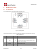


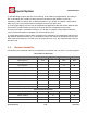


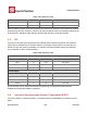
Table Of Contents
- 1.General Overview
- 1.1.Introduction
- 1.2.Features
- 1.3.Parameters
- 1.4.Ultra Low Power Technology
- 1.5.Major Applications
- 2.Hardware Overview
- 3.Pins and Definitions
- 3.1.GPIO
- 3.2.Secure Digital Input/Output Interface (SDIO)
- 3.3.Serial Peripheral Interface (SPI/HSPI)
- 3.4.Inter-integrated Circuit Interface (I2C)
- 3.5.I2S
- 3.6.Universal Asynchronous Receiver Transmitter (UART)
- 3.7.Pulse-Width Modulation (PWM)
- 3.8.IR Remote Control
- 3.9.ADC (Analog-to-digital Converter)
- 3.10.LED Light and Button
- 4.Firmware & Software Development Kit
- 5.Power Management
- 6.Clock Management
- 8.FCC Warming Statement
- This device complies with part 15 of the FCC Rules
- (1)This device may not cause harmful interference,
- (2)and this device must accept any interference re
- FCC Radiation Exposure Statement:
- This equipment complies with FCC radiation exposur
- Information to the user.
- Note: This equipment has been tested and found to
- -Reorient or relocate the receiving antenna.
- -Increase the separation between the equipment and
- -Connect the equipment into an outlet on a circuit
- -Consult the dealer or an experienced radio/TV tec
- 9.Appendix: QFN32 Package Size

ESP8266 Datasheet
Espressif Systems
Espressif Systems
June1,2015
14
/
32
2.5.
MCU
ESP8266EX is embedded with Tensilica L106 32-bit micro controller (MCU), which features extra low
power consumption and 16-bit RSIC. The CPU clock speed is 80MHz. It can also reach a maximum
value of 160MHz. Real Time Operation System (RTOS) is enabled. Currently, only 20% of MIPS has
been occupied by the WiFi stack, the rest can all be used for user application programming and
development. The following interfaces can be used to connect to the MCU embedded in
ESP8266EX:
•
Programmable RAM/ROM interfaces (iBus), which can be connected with memory controller,
and can also be used to visit external flash;
•
Data RAM interface (dBus), which can connected with memory controller;
•
AHB interface, can be used to visit the register.
2.6.
Memory Organization
2.6.1. Internal SRAM and ROM
ESP8266EX WiFi SoC is embedded with memory controller, including SRAM and ROM. MCU can visit
the memory units through iBus, dBus, and AHB interfaces. All memory units can be visited upon
request, while a memory arbiter will decide the running sequence according to the time when these
requests are received by the processor.
According to our current version of SDK provided, SRAM space that is available to users is assigned
as below:
•
RAM size < 36kB, that is to say, when ESP8266EX is working under the station mode and is
connected to the router, programmable space accessible to user in heap and data section is
around 36kB.)
•
There is no programmable ROM in the SoC, therefore, user program must be stored in an
external SPI flash.
2.6.2. External SPI Flash
An external SPI flash is used together with ESP8266EX to store user programs.Theoretically
speaking, up to 16 Mbyte memory capacity can besupported.
Suggested SPI Flash memory capacity:
•
OTA is disabled: the minimum flash memory that can be supported is 512 kByte;
•
OTA is enabled: the minimum flash memory that can be supported is 1 Mbyte.
Several SPI modes can be supported, including Standard SPI, Dual SPI, DIO SPI, QIO SPI, and Quad
SPI.