
Data Sheet
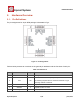


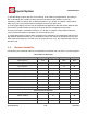


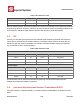
Table Of Contents
- 1.General Overview
- 1.1.Introduction
- 1.2.Features
- 1.3.Parameters
- 1.4.Ultra Low Power Technology
- 1.5.Major Applications
- 2.Hardware Overview
- 3.Pins and Definitions
- 3.1.GPIO
- 3.2.Secure Digital Input/Output Interface (SDIO)
- 3.3.Serial Peripheral Interface (SPI/HSPI)
- 3.4.Inter-integrated Circuit Interface (I2C)
- 3.5.I2S
- 3.6.Universal Asynchronous Receiver Transmitter (UART)
- 3.7.Pulse-Width Modulation (PWM)
- 3.8.IR Remote Control
- 3.9.ADC (Analog-to-digital Converter)
- 3.10.LED Light and Button
- 4.Firmware & Software Development Kit
- 5.Power Management
- 6.Clock Management
- 8.FCC Warming Statement
- This device complies with part 15 of the FCC Rules
- (1)This device may not cause harmful interference,
- (2)and this device must accept any interference re
- FCC Radiation Exposure Statement:
- This equipment complies with FCC radiation exposur
- Information to the user.
- Note: This equipment has been tested and found to
- -Reorient or relocate the receiving antenna.
- -Increase the separation between the equipment and
- -Connect the equipment into an outlet on a circuit
- -Consult the dealer or an experienced radio/TV tec
- 9.Appendix: QFN32 Package Size

ESP8266 Datasheet
Espressif Systems
Espressif Systems
June1,2015
12
/
32
Note: GPIO2, GPIO0, MTDO can be configurable as 3-bit SDIO mode.
2.2.
Electrical Characteristics
Table 3 ESP8266EX Electrical Characteristics
Parameters
Conditions
Min
Typical
Max
Unit
Storage Temperature Range
-40
Normal
125
℃
Maximum Soldering Temperature
IPC/JEDEC J-
STD-020
260
℃
Working Voltage Value
3.0
3.3
3.6
V
I/O
V
IL
/V
IH
-0.3/0.75V
IO
0.25V
IO
/3.6
V
V
OL
/V
OH
N/0.8V
IO
0.1V
IO
/N
I
MAX
12
mA
Electrostatic Discharge (HBM)
TAMB=25
℃
2
KV
Electrostatic Discharge (CDM)
TAMB=25
℃
0.5
KV
2.3.
Power Consumption
The following current consumption is based on 3.3V supply, and 25°C ambient, using internal
regulators. Measurements are done at antenna port without SAW filter. All the transmitter’s
measurements are based on 90% duty cycle, continuous transmit mode.
Table 4 Description on Power Consumption
Parameters
Min
Typical
Max
Unit
Tx802.11b, CCK 11Mbps, P OUT=+17dBm
170
mA
Tx 802.11g, OFDM 54Mbps, P OUT =+15dBm
140
mA
Tx 802.11n, MCS7, P OUT =+13dBm
120
mA
Rx 802.11b, 1024 bytes packet length , -80dBm
50
mA
Rx 802.11g, 1024 bytes packet length, -70dBm
56
mA
Rx 802.11n, 1024 bytes packet length, -65dBm
56
mA
Modem-Sleep①
15
mA
Light-Sleep②
0.9
mA
Deep-Sleep③
10
uA
Power Off
0.5
uA