
Quick Start Guide


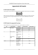
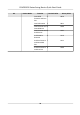


Table Of Contents
- Legal Information
- Regulatory Information
- Safety Instruction
- Available Models
- Chapter 1 Overview
- Chapter 2 Wiring
- 2.1 Components Introduction
- 2.2 Wiring Electric Supply
- 2.3 Wire Interconnecting Cable
- 2.4 Terminal Description
- 2.4.1 Master Control Board Terminal Description
- 2.4.2 Slave Control Board Terminal Description
- 2.4.3 Main Control Board Terminal Description
- 2.4.4 Main Control Board Serial Port ID Description
- 2.4.5 RS-485 Wiring
- 2.4.6 RS-232 Wiring
- 2.4.7 Wiegand Wiring
- 2.4.8 Barrier Control Wiring
- 2.4.9 Alarm Output Wiring
- 2.4.10 Fire Alarm Module Wiring
- Chapter 3 Installation
- Chapter 4 Device Settings
- Chapter 5 Activation
- Appendix A. Tips for Scanning Fingerprint
- Appendix B. DIP Switch
- Appendix C. Event and Alarm Type
- Appendix D. Table of Audio Index Related Content
- Appendix E. Error Code Description
- Appendix F. Communication Matrix and Device Command

Appendix B. DIP Switch
B.1 DIP Switch Descripon
The DIP switch is on the master lane control board. No.1 to No 8 is from the low bit to the high bit.
When the switch is towards ON, it means the switch is enabled, otherwise, the switch is o. If you
se
t the DIP switch like the gure displayed below, its binary value is 00001100, and its decimal
value is 12.
B.2 DIP Switch Corresponded Funcons
The 8-bit DIP switch corresponded funcons on the main controller are as follows:
Bit Device Mode Funcon Decimal Value Binary Value
1 to 2 Work Mode Normal Mode 0 00
Study Mode 1 01
Test Mode 2 10
3 Memory Mode Enable Memory
Mode
1 1
Disable Memory
Mode
0 0
4 Keyfob Paring
Mode
Enable Keyfob
P
aring Mode
0 0
Disable Keyfob
Paring Mode
1 1
5 to 8 Passing Mode Controlled Bi-
direcon
0 0000
Controlled
En
trance and
Prohibit Exit
1 0001
DS-K3B501S Series Swing Barrier Quick Start Guide
33