
Quick Start Guide
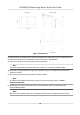


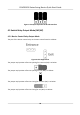
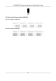


Table Of Contents
- Legal Information
- Regulatory Information
- Safety Instruction
- Available Models
- Chapter 1 Overview
- Chapter 2 Wiring
- 2.1 Components Introduction
- 2.2 Wiring Electric Supply
- 2.3 Wire Interconnecting Cable
- 2.4 Terminal Description
- 2.4.1 Master Control Board Terminal Description
- 2.4.2 Slave Control Board Terminal Description
- 2.4.3 Main Control Board Terminal Description
- 2.4.4 Main Control Board Serial Port ID Description
- 2.4.5 RS-485 Wiring
- 2.4.6 RS-232 Wiring
- 2.4.7 Wiegand Wiring
- 2.4.8 Barrier Control Wiring
- 2.4.9 Alarm Output Wiring
- 2.4.10 Fire Alarm Module Wiring
- Chapter 3 Installation
- Chapter 4 Device Settings
- Chapter 5 Activation
- Appendix A. Tips for Scanning Fingerprint
- Appendix B. DIP Switch
- Appendix C. Event and Alarm Type
- Appendix D. Table of Audio Index Related Content
- Appendix E. Error Code Description
- Appendix F. Communication Matrix and Device Command

Figure 4-3 Jumper Cap Status of RS-232 Interface
4.5 Switch Relay Output Mode (NO/NC)
4.5.1 Barrier Control Relay Output Mode
The pins of the barrier control relay on the main control board is as below:
Figure 4-4 Pin Appearance
The jumper cap's
posion of barrier opening for entrance (NO) is as below:
The jumper cap's
posion of barrier opening for exit (NO) is as below:
The jumper cap's
posion of barrier closing for entrance (NC) is as below:
The jumper cap's posion of barrier closing for exit (NC) is as below:
DS-K3B501S Series Swing Barrier Quick Start Guide
26