
Quick Start Guide


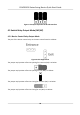
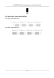

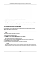

Table Of Contents
- Legal Information
- Regulatory Information
- Safety Instruction
- Available Models
- Chapter 1 Overview
- Chapter 2 Wiring
- 2.1 Components Introduction
- 2.2 Wiring Electric Supply
- 2.3 Wire Interconnecting Cable
- 2.4 Terminal Description
- 2.4.1 Master Control Board Terminal Description
- 2.4.2 Slave Control Board Terminal Description
- 2.4.3 Main Control Board Terminal Description
- 2.4.4 Main Control Board Serial Port ID Description
- 2.4.5 RS-485 Wiring
- 2.4.6 RS-232 Wiring
- 2.4.7 Wiegand Wiring
- 2.4.8 Barrier Control Wiring
- 2.4.9 Alarm Output Wiring
- 2.4.10 Fire Alarm Module Wiring
- Chapter 3 Installation
- Chapter 4 Device Settings
- Chapter 5 Activation
- Appendix A. Tips for Scanning Fingerprint
- Appendix B. DIP Switch
- Appendix C. Event and Alarm Type
- Appendix D. Table of Audio Index Related Content
- Appendix E. Error Code Description
- Appendix F. Communication Matrix and Device Command

Figure 4-1
Inializaon Jumper Cap
2. Disconnect the power and reboot the device. The device buzzer buzzes a long beep.
3. When the beep stopped, plug the jumper cap back.
4. Disconnect the power and power on the device again.
Cauon
The
inializaon of the device will restore all the parameters to the default seng and all the
device events are deleted.
Note
Make sure no persons are in the lane when powering on the device.
4.4 Switch to RS-485/RS-232 Mode
Take the Serial Port 4 and on the main control board as an example. If the Jumper cap's posion is
lik
e the picture displayed below. (The black part is the jumper cap.) The serial port is in RS-485
communicaon mode.
Figure 4-2 Jumper Cap Status of RS-485 Interface
If the Jumper cap's posion is like the picture displayed below. (The black part is the jumper cap.)
The serial port is in R
S-232 communicaon mode.
DS-K3B501S Series Swing Barrier Quick Start Guide
25