
Quick Start Guide


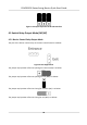
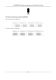


Table Of Contents
- Legal Information
- Regulatory Information
- Safety Instruction
- Available Models
- Chapter 1 Overview
- Chapter 2 Wiring
- 2.1 Components Introduction
- 2.2 Wiring Electric Supply
- 2.3 Wire Interconnecting Cable
- 2.4 Terminal Description
- 2.4.1 Master Control Board Terminal Description
- 2.4.2 Slave Control Board Terminal Description
- 2.4.3 Main Control Board Terminal Description
- 2.4.4 Main Control Board Serial Port ID Description
- 2.4.5 RS-485 Wiring
- 2.4.6 RS-232 Wiring
- 2.4.7 Wiegand Wiring
- 2.4.8 Barrier Control Wiring
- 2.4.9 Alarm Output Wiring
- 2.4.10 Fire Alarm Module Wiring
- Chapter 3 Installation
- Chapter 4 Device Settings
- Chapter 5 Activation
- Appendix A. Tips for Scanning Fingerprint
- Appendix B. DIP Switch
- Appendix C. Event and Alarm Type
- Appendix D. Table of Audio Index Related Content
- Appendix E. Error Code Description
- Appendix F. Communication Matrix and Device Command

6. P
ower on the device again.
Note
For details about the DIP switch value and meaning, see DIP S
witch Descripon.
The barrier will open automacally and turns back to the closed posion. At this circumstance,
the de
vice enters the normal mode.
4.2 Pair Keyfob (Oponal)
Pair the remote control to the device through DIP switch to open/close the barrier remotely.
Before You Start
Ask our technique supports or sales and purchase the keyfob.
Steps
1. Power o the turnsle.
2. Set the No.4 switch of the 8-digit DIP Switch on the main control board according to the gure
below.
3. P
ower on the turnsle and it will enter the keyfob pairing mode.
4. Hold the Close buon for more than 10 seconds.
The keyfob's indicator of the will ash twice if the pairing is completed.
5. Set the DIP switch as OFF, and reboot the turnsle to take eect.
Note
• You can also pair the keyfob via the client soware. For details, see Managing K
eyfob in User
Manual of iVMS-4200 AC Client Soware.
• Only one turnsle can pair the keyfob. If mulple turnsles are in the pairing mode, the
k
eyfob will select only one of them to pair.
• For details about DIP switch value and meaning, see DIP Switch .
4.3 Inialize Device
Steps
1. Remove the jumper cap of inializaon pin on the main control board.
DS-K3B501S Series Swing Barrier Quick Start Guide
24