
Quick Start Guide


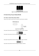


Table Of Contents
- Legal Information
- Regulatory Information
- Safety Instruction
- Available Models
- Chapter 1 Overview
- Chapter 2 Wiring
- 2.1 Components Introduction
- 2.2 Wiring Electric Supply
- 2.3 Wire Interconnecting Cable
- 2.4 Terminal Description
- 2.4.1 Master Control Board Terminal Description
- 2.4.2 Slave Control Board Terminal Description
- 2.4.3 Main Control Board Terminal Description
- 2.4.4 Main Control Board Serial Port ID Description
- 2.4.5 RS-485 Wiring
- 2.4.6 RS-232 Wiring
- 2.4.7 Wiegand Wiring
- 2.4.8 Barrier Control Wiring
- 2.4.9 Alarm Output Wiring
- 2.4.10 Fire Alarm Module Wiring
- Chapter 3 Installation
- Chapter 4 Device Settings
- Chapter 5 Activation
- Appendix A. Tips for Scanning Fingerprint
- Appendix B. DIP Switch
- Appendix C. Event and Alarm Type
- Appendix D. Table of Audio Index Related Content
- Appendix E. Error Code Description
- Appendix F. Communication Matrix and Device Command

Chapter 4 Device Sengs
Aer installaon and wiring completed, you should set the barriers closed posion (study mode)
before entering the working mode.
You can also set the test mode, normal mode, passing mode and memory mode, pair the keyfob,
inialize the hardware, switching between RS-485 communicaon mode and RS-232
communicaon mode, and view relay output NO/NC diagram by seng the DIP switch on the main
control board.
• Study Mode: The barrier will learn the closed posion.
• Normal Mode: The device will work properly.
• Test Mode: Test mode is the same as the normal mode except that the device cannot report the
alarm, the event, or the people counng informaon to the center.
• Passing Mode: There are 9 passing modes, including controlled bi-direcon, controlled entrance
and prohibited exit, controlled entrance and free exit, free bi-direcon, free entrance and
controlled exit, free entrance and prohibited exit, prohibited bi-direcon, prohibited entrance
and free exit.
• Memory Mode: By default, the memory mode is enabled. When mulple cards are presented
and authencated, it allows mulple persons passing through the lane. When it counts the
passing people number is equal to the card presented mes, or no person passing through the
lane aer the last person passing, the barriers will be closed.
Note
You can also set the DIP switch on the main control board to control the entrance and exit
c
ontrolling type, keyfob pairing, etc. For details about the DIP switch value, see DIP Switch .
4.1 Set Closed Posion
Enter the study mode through DIP switching to set the closed posion of the device barrier.
St
eps
1. Set The No.1 and No.2 switches of the 8-digit DIP Switch on the main control board by referring
the following gure to enter the study mode.
2. Adjus
t the closed posion of the barrier.
3. Power on the device.
The device will remember the current posion (closed posion) automacally.
4. P
ower o the device.
5. Set the No.1 and No.2 switches of the 8-digit DIP Switch on the main control board by referring
to the following gure.
DS-K3B501S Series Swing Barrier Quick Start Guide
23