
Quick Start Guide
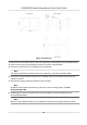


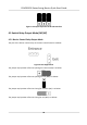
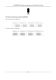


Table Of Contents
- Legal Information
- Regulatory Information
- Safety Instruction
- Available Models
- Chapter 1 Overview
- Chapter 2 Wiring
- 2.1 Components Introduction
- 2.2 Wiring Electric Supply
- 2.3 Wire Interconnecting Cable
- 2.4 Terminal Description
- 2.4.1 Master Control Board Terminal Description
- 2.4.2 Slave Control Board Terminal Description
- 2.4.3 Main Control Board Terminal Description
- 2.4.4 Main Control Board Serial Port ID Description
- 2.4.5 RS-485 Wiring
- 2.4.6 RS-232 Wiring
- 2.4.7 Wiegand Wiring
- 2.4.8 Barrier Control Wiring
- 2.4.9 Alarm Output Wiring
- 2.4.10 Fire Alarm Module Wiring
- Chapter 3 Installation
- Chapter 4 Device Settings
- Chapter 5 Activation
- Appendix A. Tips for Scanning Fingerprint
- Appendix B. DIP Switch
- Appendix C. Event and Alarm Type
- Appendix D. Table of Audio Index Related Content
- Appendix E. Error Code Description
- Appendix F. Communication Matrix and Device Command

Figure 3-2 Dimension
1. Pr
epare for the installaon tools, check the components, and prepare for the installaon base.
2. Draw a central line on the installaon surface of the le or right pedestal.
3. Draw other parallel lines for installing the other pedestals.
Note
The distance between the nearest two line is L+200 mm. L represents the lane width.
4. Drill holes on the gr
ound according to the installaon holes on the pedestals and insert the
expansion sleeves.
5. Bury interconnecng cables for pedestal communicaon.
Note
For detailed informaon about burying and wiring interconnecng cables, see Wire
Interconnecng Cable .
6. Acc
ording to the entrance and exit marks on the pedestals, move the pedestals to the
corresponded posions.
Note
Make sure the installaon holes on the pedestals and the base are aligned with each other.
DS-K3B501S Series Swing Barrier Quick Start Guide
21