
Quick Start Guide


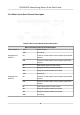
Table Of Contents
- Legal Information
- Regulatory Information
- Safety Instruction
- Available Models
- Chapter 1 Overview
- Chapter 2 Wiring
- 2.1 Components Introduction
- 2.2 Wiring Electric Supply
- 2.3 Wire Interconnecting Cable
- 2.4 Terminal Description
- 2.4.1 Master Control Board Terminal Description
- 2.4.2 Slave Control Board Terminal Description
- 2.4.3 Main Control Board Terminal Description
- 2.4.4 Main Control Board Serial Port ID Description
- 2.4.5 RS-485 Wiring
- 2.4.6 RS-232 Wiring
- 2.4.7 Wiegand Wiring
- 2.4.8 Barrier Control Wiring
- 2.4.9 Alarm Output Wiring
- 2.4.10 Fire Alarm Module Wiring
- Chapter 3 Installation
- Chapter 4 Device Settings
- Chapter 5 Activation
- Appendix A. Tips for Scanning Fingerprint
- Appendix B. DIP Switch
- Appendix C. Event and Alarm Type
- Appendix D. Table of Audio Index Related Content
- Appendix E. Error Code Description
- Appendix F. Communication Matrix and Device Command

Figure 2-2 Components 2
Note
If the turnsle contains two lanes, standing at the entrance posion, the IR boards on the le
pedestal are the IR sending boards. The IR boards on the right pedestal are the IR receiving boards.
The IR boards on the le side of the middle pedestal are the IR receiving boards, while the IR
boards on the right side of the middle pedestal are the IR sending boards.
2.2 Wiring Electric Supply
Wire electric supply with the switch in the pedestal. Terminal L and terminal N are on the switch,
while t
erminal PE should connect to a ground wire (yellow and green wire).
DS-K3B501S Series Swing Barrier Quick Start Guide
4