
Quick Start Guide


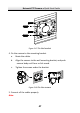


Table Of Contents
- 1 Overview
- 2 Installation
- 2.1 Installing the Memory Card
- 2.2 Installing DE1Axxx(I) Series PTZ Camera
- 2.3 Installing DE2Axxx(I) Series PTZ Camera
- 2.4 Installing DE2xxx(I) Series PTZ Camera
- 2.5 Installing DE3xxx Series PTZ Camera
- 2.6 Installing DY3xxx Series PTZ Bullet Camera
- 2.7 Installing DE4AxxxI Series PTZ Camera
- 2.8 Installing DE3AxxxI Series PTZ Camera
- 2.9 Installation of Network Cable Water-proof Jacket
- 2.10 Installation of Water-proof Tape
- 3 Setting the PTZ Camera over the LAN
- 4 Accessing via Web Browser
- 5 Operating via Hik-Connect App

Network PTZ Camera·Quick Start Guide
46
and connect cables through the wall and the cable hole on the
bracket.
For the cables routed on the wall surface, you need to route
the cables through the middle slot on the bottom of the back
box, as shown in Figure 2-66.
Cable slot
Figure 2-66 Wiring on the wall
3. Fix the bracket to the target position with four screws (PA4×25) in
the package (supplied), making sure the direction of the sign ”UP”
is upward as shown in Figure 2-67.
Notes:
For cement wall, you need to use the expansion screw to fix the
bracket. The mounting hole of the expansion pipe on the wall
should align with the mounting hole on the bracket.
For wooden wall, you can just use the self-tapping screw to fix
the bracket.