5. Pulse XT 40 ARF Assembly manual Specifications Wingspan.................................. 60.7 in (1540.5mm) Wing Area............................... 667 sq in (43 sq dm) Length............................................. 50 in (1270mm) Weight................. Glow: 5.5–6.25 lb (2.5 kg–2.8 kg) ..... Electric w/o battery: 4.7–5lb (2.1–2.
Table of Contents UltraCote Covering Colors . . . . . . . . . . . . . . . . . . . . . . . . . . . . . . . . . . . . . . . . . . . . . . . . . . . . . . . . . . . 3 Radio and Power Systems Requirements . . . . . . . . . . . . . . . . . . . . . . . . . . . . . . . . . . . . . . . . . . . . . . . . 3 Contents of Kit . . . . . . . . . . . . . . . . . . . . . . . . . . . . . . . . . . . . . . . . . . . . . . . . . . . . . . . . . . . . . . . . . . . . 3 Required Items for Electric Installation . . . . . . . . .
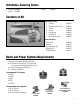
UltraCote® Covering Colors • True Red HANU866 • Silver HANU881 • White HANU870 Contents of Kit A F D B C E G Replacement Parts A. Fuselage B. Wing w/o Aluminum Tube C. Tail Set D. Canopy E. Landing Gear F. Painted Cowl G.
Required Items for Electric Installation • Female Deans connector w/wire • Male Deans connector (3) • Soldering iron • Solder • Phoenix-60 Speed Control (CSEPHX60) • Electric Propeller,13 x 6.5E (APC13065E) • Heat shrink tubing: 1/4" (6mm) • 4200mAh 2S2P 7.
Limited Warranty & Limits of Liability Pursuant to this Limited Warranty, Horizon Hobby, Inc. will, at its option, (i) repair or (ii) replace, any product determined by Horizon Hobby, Inc. to be defective. In the event of a defect, these are your exclusive remedies. This warranty does not cover cosmetic damage or damage due to acts of God, accident, misuse, abuse, negligence, commercial use, or modification of or to any part of the product.
Inspection or Repairs If your product needs to be inspected or repaired, please call for a Return Merchandise Authorization (RMA). Pack the product securely using a shipping carton. Please note that original boxes may be included, but are not designed to withstand the rigors of shipping without additional protection. Ship via a carrier that provides tracking and insurance for lost or damaged parcels, as Horizon Hobby, Inc. is not responsible for merchandise until it arrives and is accepted at our facility.
Warranty Information Horizon Hobby, Inc. guarantees this kit to be free from defects in both material and workmanship at the date of purchase. This warranty does not cover any parts damage by use or modification. In no case shall Horizon Hobby’s liability exceed the original cost of the purchased kit. Further, Horizon Hobby reserves the right to change or modify this warranty without notice.
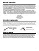
Section 1: Aileron Installation Required Parts • Wing panel (right and left) • Aileron (right and left) • Servo w/hardware (2) • Clevis w/retainer (2) • CA hinge (8) • Servo extension, 6" (152mm) • Aileron linkage, 4" (102mm) (2) • Control horn w/backplate (2) • 2mm x 16mm screw (4) • 2mm x 12mm screw (2) Note: The hole will allow the CA to penetrate the hinge farther into the surface, providing a better bond between the hinge and wood. Step 3 Slide the hinges into the aileron.
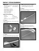
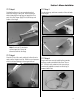
Section 1: Aileron Installation Step 5 Step 7 Position the aileron so it can move freely and not . bind at the wing tip or wing root. Deflect the aileron without changing the hinge gap, and apply thin CA to . each of the four hinges. Apply CA to both the top and bottom of the hinges. Flex the aileron up and down a number of times to break in the hinges. Note: Do not use CA accelerator on the hinges; the CA must be allowed to soak into the hinge.
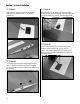
Section 1: Aileron Installation Step 9 Step 11 Slide one of the longer pushrod wires into the wing. Attach the servo extension to the “Z” bend of the . pushrod wire. Place the servo into the opening with the servo output towards the trailing edge of the wing. Use a felt-tipped pen to mark the locations for the four servo mounting screws. Step 12 Remove the servo and drill the locations for the servo mounting screws using a 1/16" (1.5mm) drill bit. .
Section 1: Aileron Installation Step 13 Secure the servo using the screws provided with . the servo. Note: You may want to use tape at the wing tip and wing root to hold the aileron in position for the next few steps. Step 16 Plug the aileron servo into the radio system. With the radio on, center the aileron stick and trim. Position the aileron servo arm parallel to the hinge line. Thread the clevis so the pin in the clevis is aligned with the trailing edge of the wing.
Section 1: Aileron Installation Step 18 Step 19 Use a 5/64" (2mm) drill bit to drill the locations for the control horn screws. Place a few drops of thin CA into each hole to harden the underlying wood. This will help in preventing the wood from crushing when tightening the control horn screws. Attach the control horn using two 2mm x 16mm screws, a 2mm x 12mm screw and the control horn backplate. The shorter screw goes towards the trailing edge of the aileron.
Section 2: Hinging the Stabilizer Required Parts • Stabilizer • Elevator (right and left) • Elevator joiner wire • Control horn w/backplate • 2mm x 12mm screw (3) Step 3 Mix up a small amount of 6-minute epoxy. Apply epoxy to the hole and groove of the elevator. Also apply epoxy to the joiner wire where it will contact the elevator half. Slide the joiner wire into position and use masking tape to hold it in position until the epoxy cures.
Section 2: Hinging the Stabilizer Step 6 Step 8 Drill a 1/16" (1.5mm) hole in the center of each hinge slot in both the elevators and stabilizer. Prepare six CA hinges by placing a T-pin in the center of each hinge. Slide the hinges into the elevators until the T-pins are resting on the leading edge of the elevator. Since the holes are pre-drilled in the elevator, go . ahead and install the control horn using three . 2mm x 12mm screws. Step 7 Slide the elevators onto the stabilizer.
Section 3: Hinging the Rudder Required Parts • Rudder • Fin • Tail wheel assembly • Tail wheel 1" (25mm) • CA hinge (2) • 2mm wheel collar w/setscrew • Control horn w/backplate • 2mm x 12mm screw (3) Step 2 Use a hobby knife or side cutters to trim the nylon bearing as shown. Drill three 5/64" (2mm) holes in the bearing to give the epoxy something to grab on to when it gets glued into the rudder post.
Section 3: Hinging the Rudder Step 6 Step 8 Test fit the rudder and fin together. Make sure to insert the tail gear wire into the rudder. When satisfied with the fit, mix up a small amount of 6-minute epoxy and apply it to the tail gear wire and the corresponding hole in the rudder. Slide the rudder back into position against the fin. Attach the tail wheel using the 2mm wheel collar . and setscrew. Use threadlock on the setscrew to prevent it from coming loose in flight due to vibration.
Section 4: Landing Gear Installation Required Parts • Fuselage • Landing gear • 4mm nut (6) • 4mm locknut (2) • 6-32 x 1/2" socket head screw (3) • 4-40 blind nut (4) • #6 washer (3) 3 • 2 /4" (70mm) wheel (2) • Wheel pant (right and left) • 4-40 x 3/8" socket head bolt (4) • 4mm x 40mm socket head bolt (2) Step 2 Slide a 4mm x 40mm socket head bolt into a wheel. Slide a 4mm washer onto the bolt then thread a 4mm nut onto the bolt.
Section 4: Landing Gear Installation Step 4 Step 6 Position the inner 4mm nut so there is about 7/16" (12mm) between the wheel nut and landing gear. . Tighten the 4mm locknut onto the screw. The . distance may require some adjustment once the . wheel pants have been installed. Place the wheel pant over the wheel. Position the wheel pant so it is parallel to the fuselage centerline. Mark the location for the two screws from the back of the wheel pant using a felt-tipped pen.
Section 4: Landing Gear Installation Step 7 Step 9 Use a 9/64" (3.5mm) drill bit to drill the two locations . for the screws. Secure the wheel pant to the landing gear using two . 4-40 x 3/8" socket head screws. Make sure to use threadlock to prevent the screws from loosening . during flight. Step 8 Install two 4-40 blind nuts inside the wheel pants through the holes drilled in the previous step. Step 10 Check that the wheel can spin freely without rubbing on the wheel pant.
Section 5: Servo Installation Required Parts • Fuselage • 23 3/8" (594mm) rudder pushrod • 22 1/2" (572mm) elevator pushrod wire • Clevis w/retainer Step 2 Use a 1/16" (1.5mm) drill bit to drill the locations for the screws. Place a drop of thin CA into each of the holes to harden the surrounding wood. Required Tools and Adhesives • Drill • Felt-tipped pen • Switch harness • Standard servo (3) • Phillips screwdriver • Drill bit: 1/16" (1.
Section 5: Servo Installation Step 4 Step 7 Repeat Steps 1 through 3 to install the rudder and . elevator servos. Plug the servos, extensions and switch harness into the receiver. Plug the receiver battery and switch harness together. Place the receiver and receiver battery into the fuselage. Step 5 Install the switch harness on the side of the fuselage using the switch harness hardware. Step 8 Route the receiver antenna to the rear of the fuselage using the pre-installed antenna tube.
Section 5: Servo Installation Step 9 23 3/ Attach the 8" (594mm) rudder pushrod to the servo arm using the “Z” bend in the pushrod. You may need to use a 5/64" (2mm) drill bit to enlarge the hole in the servo arm to accept the wire. Step 11 Slide a clevis retainer onto a clevis. Thread the clevis onto the rudder pushrod. Step 12 Step 10 Turn the radio system on and center the rudder stick and rudder trim. Slide the pushrod wire into the pushrod tube.
Section 6A: Tail Installation Required Parts • Fuselage • Stabilizer assembly • #4 washer Step 3 • Rudder assembly • 4-40 locknut (2) Secure the tail assembly to the fuselage using two 4-40 locknuts and two #4 washers. Required Tools and Adhesives • Adjustable wrench Step 1 Carefully slide the threaded rods from the rudder assembly into the stabilizer assembly. Note: Do not over-tighten the nuts and crush the fuselage. Step 4 Connect the rudder clevis to the rudder control horn.
Section 6A: Tail Installation Step 5 Repeat Step 4 for the elevator.
Section 6B: Gluing the Tail (Optional) Required Parts • Fuselage w/tail installed Required Tools and Adhesives • Adjustable wrench • Felt-tipped pen • Hobby knife • 30-minute epoxy • Straight edge Step 2 Remove the tail from the fuselage. Use a straight . edge and hobby knife to trim the covering about . 1/16" (1.5mm) inside the lines drawn on the top and bottom of the stabilizer. This section is optional and describes how to permanently glue the tail section to the fuselage.
Section 7A: Electric Motor Installation Required Parts • Fuselage • Plywood battery tray • Hook and loop strap • Cowling • 4-40 x 3/8" socket head screw (2) • 6-32 x 1 7/8" screw (4) • 1" (25mm) aluminum motor spacer (4) • Hook and loop (adhesive back) • #2 x 1/2" sheet metal screw (2) Step 2 Attach the X-mount to the back of the motor using the hardware provided with the motor. Remember to put a drop of threadlock on each of the screws to prevent them from vibrating loose.
Section 7A: Electric Motor Installation Step 4 Step 7 Build a wiring harness for the batteries using a female connector and two male connectors. Follow the wiring in the photo so the motor sees the voltage increase of the two batteries. Prepare the battery tray by applying two pieces of self adhesive hook and loop to the battery tray. Start the hook and loop directly behind the holes in the tray. Step 5 Solder the appropriate connectors onto the speed control.
Section 7A: Electric Motor Installation Step 9 Step 11 Remove the hatch from the bottom of the fuselage. Slide the battery tray into the fuselage with the hook and loop facing towards the bottom. The rear of the battery tray will key into the former. Use two 4-40 x 3/8" socket head screws to secure the front of the battery tray. Turn on the radio system. Plug the wiring harness assembled in Step 4 into the batteries and speed control.
Section 7B: Glow Engine Installation Required Parts • Fuselage • Engine mount (2) • Cowling • Fuel tank • 6-32 locknut (4) • #6 washer (4) • Clevis w/retainer • Throttle pushrod • 3mm x 6mm screw • Thick foam • 6-32 x 3/4" screw (4) • 6-32 x 1 1/4" screw (4) • Pushrod connector w/backplate • #2 x 1/2" sheet metal screw (4) • 4-40 x 1/2" socket head screw Step 2 Position the engine on the engine mount so the drive washer is 4" (102mm) ahead of the firewall.
Section 7B: Two-Stroke Engine Installation Step 4 Mount the engine to the mount using four 6-32 x screws, four #6 washers and four 6-32 locknuts. Step 7 1 1/ 4" Turn on the radio system and center the throttle stick and trim. Slide the pushrod into the brass connector. Place the servo horn onto the servo so the horn is perpendicular to the servo centerline. Step 5 Slide a clevis retainer onto a clevis, and then thread the clevis onto the throttle pushrod.
Section 7B: Two-Stroke Engine Installation Step 10 Step 12 Locate the fuel tank. Hold the tank up to a strong light to determine which direction the vent line is facing. This will be the top of the tank. The red tube is attached to the vent line of the tank. Place the tank inside the fuselage with the vent towards the top of the fuselage. Place the fuselage hatch into position and secure it using the 4-40 x 1/2" socket head screw.
Section 8: Final Assembly Required Parts • Fuselage • Wing • Wing bolt plate • Wing tube 1 • 1/4-20 x 1 /2" nylon bolt (2) • 1 7/8" (48mm) wing dowel (2) • 1 5/16" (33mm) wing dowel • 2mm x 8mm sheet metal screw (4) Required Tools and Adhesives • Thin CA • Phillips screwdriver Step 1 Step 3 Apply any remaining decals onto the aircraft using either the box for location or your imagination. Step 4 Slide the 1 7/8" (48mm) wing dowel into one of the wing panels.
Section 8: Final Assembly Step 6 Step 7 Slide the remaining wing panel onto the wing tube aligning the dowel into the panel. Slide the 1/4-20 x 1 1/2" wing bolts through the wing bolt plate. Position the wing dowels into the holes in the fuselage. Slide the bolts through the wing and tighten them to secure the wing to the fuselage.
Control Throws The amount of control throw should be adjusted as closely as possible using mechanical means, rather than making large changes electronically at the radio. By moving the position of the clevis at the control horn toward the outermost hole, you will decrease the amount of control throw of the control surface. Moving it toward the control surface will increase the amount of throw.
Recommended Center of Gravity (CG) An important part of preparing the aircraft for flight is properly balancing the model. This is especially important when various engines are mounted. Caution: Do not inadvertently skip this step! The recommended Center of Gravity (CG) location for . the Pulse XT is 2 3/4" (70mm) behind the leading edge . of the wing against the fuselage. Make sure the aircraft . is inverted when measuring the CG. If necessary, move .
Adjusting the Engine (Glow) Step 1 Step 3 Completely read the instructions included with your engine and follow the recommended break in procedure. Before you fly, be sure that your engine idles reliably, transitions and runs at all throttle settings. Only when this is achieved should any plane be considered ready for flight. Step 2 At the field, adjust the engine to a slightly rich setting at full throttle and adjust the idle and low-speed needle so that a consistent idle is achieved.
Glossary of Terms • Ailerons: Each side of this airplane has a hinged control surface (aileron), located on the trailing edge of the wing. Move the aileron stick on the transmitter left, the left aileron moves up and the right aileron moves down. Moving the left aileron up causes more drag and less lift, causing the left wing to drop down. When the right aileron moves down, more lift is created, causing the right wing to rise. This interaction causes the airplane to turn or roll to the left.
2006 Official AMA National Model Aircraft Safety Code GENERAL 1) I will not fly my model aircraft in sanctioned events, air shows or model flying demonstrations until it has been proven to be airworthy by having been previously, successfully flight tested. 2) I will not fly my model higher than approximately 400 feet within 3 miles of an airport without notifying the airport operator. I will give right-of-way and avoid flying in the proximity of full-scale aircraft.
2006 Official AMA National Model Aircraft Safety Code 5) Flying sites separated by three miles or more are considered safe from site-to site interference, even when both sites use the same frequencies. Any circumstances under three miles separation require a frequency management arrangement, which may be either an allocation of specific frequencies for each site or testing to determine that freedom from interference exists.
5. © 2006 Horizon Hobby, Inc.. 4105 Fieldstone Road. Champaign, Illinois 61822. (877) 504-0233. horizonhobby.