848EW093A0 (603) G200PU OWNER'S MANUAL Model: Model code: X374320000 Thank you for purchasing a KOMATSU ZENOAH engine. ● Please read this Service Manual thoroughly and use the engine correctly. (For safety reasons, please contact your sales dealer prior to using the engine if there is something about it that you do not understand.) ● This engine has been designed for radio control airplanes. Please use it in conjunction with the manuals for the models or radio control equipment you will be using.
CONTENTS Specifications .......................................................................3 Safety Precautions ...............................................................4 Engine Assembly .................................................................6 DC Ignition Unit Mounting ....................................................7 Fuel and Piping ....................................................................8 Throttle Linkage and Engine Mounting ................................
SPECIFICATIONS NO. ITEM 1. Engine model G200PU SPECIFICATIONS 2. Displacement 20.1cm3 3. Bore x stroke ø32mm x 25mm 4. Weight 990g (not including DC Ignition Unit) 5. Carburetor type WT-811 6. Ignition Battery ignition; digital control 7. Sparkplug Champion Y82 8. Revolution direction Counterclockwise (from PTO side) 9. Starting method External motor 10. Sensor spacing 0.8 ~ 1.2mm (1.0mm ± 0.2mm) 11. Fuel consumption 1.0 / 9000rpm (at full throttle) 12.
SAFETY PRECAUTIONS ● These safety precautions are to prevent you and those in the vicinity from incurring harm or damage. Make sure to observe these precautions and to constantly strive to ensure safety. ● Safe use of the engine is your personal obligation and responsibility. Constantly take care to act with good judgment as you enjoy your hobbies. • Make sure never to touch the propeller when it is rotating.
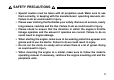
SAFETY PRECAUTIONS • Special caution must be taken with all propellers used. Make sure to use them correctly, in keeping with the manufacturers’ operating manuals, etc. Failure to do so could result in injury. • Please wear clothing that facilitates your safety. Remove all scarves, overly long sleeves, neckties and the like. Failure to do so could result in injury. • Please check to ensure that the direction in which the engine’s throttle linkage operates and the amount it operates are correct.
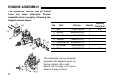
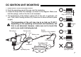
ENGINE ASSEMBLY The carburetor, muffler, and air funnel have not been attached. Please assemble them correctly, following the diagram shown below. No. (3) (1) (2) (6) (7) (4) (5) 1. 2. 3. 4. 5. 6. 7. Part Part no. Bolt 01252-30540 Muffler 848EW015A0 Gasket 1140-13141 Gasket 848H7014C1 Carburetor set 848EW09710 Air funnel 848ES08300 Bolt 8488455000 The carburetor can be mounted anywhere 90 degrees apart on the top, bottom, left or right. Mount the linkage at a place where it is easy to do so.
DC IGNITION UNIT MOUNTING 1. Make sure to install the power switch. 2. Push the sparkplug cap all the way over the sparkplug. 3. Fixate the body within the fuselage, as shown in the diagram. Make sure that the sponge, cloth or the like is not enclosed. 4. The temperature of the bottom surface (D) of the unit, in particular, will rise. Thus, when fixating surface (D), make sure to leave sufficient space (a gap).
FUEL AND PIPING ● For gasoline, please use either regular or high octane, for cars. (The octane number should be 85 or higher.) ● For oil, use a high-performing mixed lubrication type of 2-cycle engine oil and make the fuel volume ratio 1 (oil) to 25-40 (gasoline). ● For fuel piping, refer to the diagram shown below. (7) (1) (5) (4) (2) (5) (8) (3) (6) • Do not use a silicon tube. • Clip the weight so that it does not shift when the engine is running. 1. 2. 3. 4. 5.
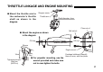
THROTTLE LINKAGE AND ENGINE MOUNTING ● Mount the throttle arm to the carburetor’s throttle shaft as shown in the diagram. Stopper screw Throttle arm Shaft diameter: 4mm Claw nut x4 ● Mount the engine as shown in the diagram. CG line M4 bolt x4 CG line Gloves Engine mount 10cm Tightening torque: 90kg-cm (8.8 N-m) 9kg ● For propeller mounting, use the wrench provided and make sure not to over-tighten the bolts.
ITEMS TO CONFIRM BEFORE STARTING THE ENGINE ● Please determine the propeller to use in keeping with the airplane’s size, gross weight, and flight characteristics. If necessary, consult with someone who has the proper experience. Guidelines for an APC propeller: about 8.
STARTING THE ENGINE ● Close the choke lever and open the throttle valve 10% to 15%. ● Pressing the tip of the starter to the engine’s spinner, press the start switch for 1-2 sec and let the engine rotate. ● If the engine makes an explosive sound, suspend the starting operation and start by opening the choke lever and rotating the engine using the starter. (Opening or closing the choke lever during engine operation is prohibited.
ADJUSTMENTS FOLLOWING STARTUP (A) ADJUSTING THE IDLING ● Following startup, set the number of engine rotations for idling at about 2000rpm, rotate the L needle to the right (to reduce fuel), and search for the position for the highest number of rotations. From that position, turn the L needle about 1/4 (90°) to the left (to increase fuel) and set the number of rotations for idling with the idle screw or the transmitter.
TRIAL RUN ● Different from a glow engine, this engine does not require any special trial run. ● After 5~10 tanks (2~3 hours), adjust the carburetor’s L and H needles if necessary. ● After about 5 hours’ running, the highest number of rotations will be slightly above the initial value, owing to the engine having been conditioned. STOPPING THE ENGINE ● To stop the engine, either use the transmitter to achieve full throttle or turn the battery switch off.
INSPECTION To ensure safe use of the engine, make sure of the items specified in the table below. Before using Every 25h Every 100h Leakage & breakage ✔ ✔ ✔ Idling stability Sparkplug ✔ – ✔ ✔ ✔ ✔ Cylinder Piston/Ring Muffler tightening bolt Ignition unit – – ✔ ✔ ✔ ✔ ✔ ✔ ✔ ✔ ✔ ✔ Propeller hub (Stud) ✔ ✔ ✔ Crankshaft – – ✔ DC unit wiring ✔ ✔ ✔ Stud/Nut ✔ ✔ ✔ Item 14 Inspection Cylinder, carburetor, muffler, crankcase, Fuel pipe, etc.
TIGHTENING TORQUE CHART Part Cylinder Sparkplug Muffler Crankcase Insulator Carburetor Sensor Stud (hub) Nut (propeller) Engine mount Screw Size M4 (P0.7) M10 (P1.0) M5 (P0.8) M4 (P0.7) M4 (P0.7) M5 (P0.8) M4 (P0.7) M6 (P1.0) M8 (P1.25) M4 (P0.7) Tightening Torque N-m Kg-cm Remarks 3.9 40 7.8 80 Using the tool provided 8.5 90 3.9 40 3.4 35 3.4 35 1.7 20 9.8 100 Using a piston stopper & LOCK TIGHT 9.8 100 Using the tool provided 2.0 20 PROPELLER HUB REMOVAL ● Remove the propeller hub as specified below.
CAUTION: ● Do not remove the sensor. ● Make sure that nuts turned with a lug wrench are nuts on the propeller hub side. ● Use a commercial puller of the appropriate size. ● When reassembling the start bolt, apply (LOCK TIGHT) to the M6 thread part. OTHER INFORMATION This information is to enable our customers to enjoy radio control airplanes more, but all customers must take responsibility if they implement it.
PARTS LIST KEY# PART NUMBER DESCRIPTION Q'TY/ REMARKS UNIT 1 2 3 4 5 6 7 8 848EW08100 3306-81380 3080-81120 3310-81130 3304-81140 1172-81150 2850-81290 3310-81260 CARBURETOR ASSY • SCREEN • COVER • SCREW • GASKET • DIAPHRAGM • GASKET • DIAPHRAGM 1 1 1 1 1 1 1 1 10 3310-81280 • METERING COVER 1 12 13 14 15 16 17 18 19 20 21 22 23 24 25 26 27 28 29 30 31 32 33 34 35 36 2867-81270 3356-81310 1480-81420 3310-81230 3310-81240 3310-81250 2630-81330 3350-81380 848EW081T0 2670-81410 2880-81470 1282-8134
PARTS LIST 18
PARTS LIST KEY# PART NUMBER DESCRIPTION 1 848EW012A1 CYLINDER 2 848EW012B0 GASKET, cylinder 3 8488441800 BOLT 4 848EW014A0 INSULATOR 5 848EW014B1 GASKET, insulator 6 848EW02110 CRANKCASE COMP. 7 848EW021D0 GASKET, case 8 1155-21240 BEARING 9 06034-06001 BEARING 10 T1600-21240 BEARING 11 04065-02812 SNAPRING 12 T1600-21210 SEAL 13 3310-72150 BOLT 14 848EW041A1 PISTON 15 T2071-41210 RING 16 1101-41310 PISTON PIN 17 1260-41320 SNAP RING 18 5500-41410 BEARING 19 1101-41340 WASHER 20 848EW04200 CRANKHAFT COMP.
WARRANTY ● Applicable Range This warranty applies only to the engines and parts manufactured by K0MATSU ZENOAH and sold directly or through distributors. ● Range of Warranty This warranty shall apply only to trouble resulting from material defects and inferior assemblies that K0MATSU ZENOAH acknowledges. ● Method and Extent of Compensation 1) Repair or replacement through the distributor, etc.