
User Manual

9
Required Parts
• Fuselage assembly • Stabilizer/elevator (2)
• 6
3
/
8
-inch (162mm) joiner • #6 washer (4)
• Tail wheel assembly • 2-56 nut (4)
• 4-40 locknut (3)
• Large strut support bracket (2)
• Small strut support bracket (2)
• #6 x 5/8-inch sheet metal screws (2)
• 4-40 x 5/8-inch socket head screw (3)
• Support rod w/clevis, 10-inch (254mm) (2)
• Support rod w/clevis, 9
1
/
2
-inch (241mm) (2)
• 6-32 x 3/4-inch socket head screw (4)
Required Tools and Adhesives
• Threadlock
• Hex wrench: 3/32-inch, 7/64-inch
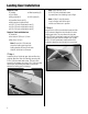
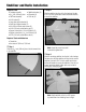
Step 1
Slide the 6
3
/
8
-inch (162mm) joiner into the forward hole
in the stabilizer.
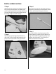
Step 2
Slide the stabilizer into the slot in the fuselage. Use two
6-32 x 3/4-inch socket head screws and two #6 washers
to secure the stabilizer.
Note: Leave the screws loose until
instructed to tighten them.
Step 3
Slide the remaining stabilizer into the slot in the fuselage.
The tubes from the first stabilizer will key into the second
stabilizer. Use two 6-32 x 3/4-inch socket head screws
and two #6 washers to secure the stabilizer. Once all four
screws have been started, tighten each one, but avoid
crushing the underlying wood.
Note: Use threadlock on the four 6-32 screws
to prevent them from vibrating loose in flight.
Stabilizer and Radio Installation