
User Manual


16
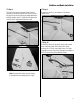
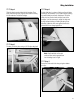
Check the operation of the control surfaces using the radio
system. Make sure all the control surfaces are centered. If
not, adjust the clevises as necessary, making sure to apply
threadlock and tighten the locking nut against the clevises
once the control surfaces have been centered.
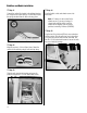
The amount of control throw should be adjusted as closely
as possible using mechanical means, rather than making
large changes electronically at the radio. By moving
the position of the clevis at the control horn toward the
outermost hole, you will decrease the amount of control
throw of the control surface. Moving it toward the control
surface will increase the amount of throw; moving the
pushrod wire at the servo arm will have the opposite
effect. Moving it closer to center will decrease throw,
and away from center will increase throw. Work with a
combination of the two to achieve the closest or exact
control throws listed.
Aileron:
High Rate: 1
1
/
8
-inch (28mm) up
1
1
/
8
-inch (28mm) down
Low Rate: 3/4-inch (19mm) up
3/4-inch (19mm) down
Note: Aileron throw is measured at the trailing
edge of the aileron nearest the fuselage.
Elevator:
High Rate: 2-inch (51mm) up/down
Low Rate: 1
1
/
4
-inch (32mm) up/down
Note: Elevator throw is measured
at the trailing edge of the elevator
next to the fuselage.
Rudder:
High Rate: 2
1
/
4
-inch (57mm) left/right
Low Rate: 1
1
/
2
-inch (38mm) left/right
Note: Rudder throw is measured
at the bottom of the rudder.
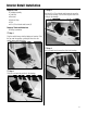
Adjust the throttle servo and linkage at this time as well.
With the throttle stick up and trim up, make sure the
carburetor is open. With the stick down and trim up, the
carbuetor should be open slightly, allowing the engine to
idle. With the stick down and trim down, the carburetor
will be closed, which will stop the engine. If the throttle
servo is binding at fully open or closed, adjust the throw
at the radio to prevent binding. Binding can drain your
receiver battery quickly or damage your throttle servo,
causing the radio or servo to fail in flight.
An important part of preparing the aircraft for flight is
properly balancing the model. This is especially important
when various engines are mounted.
Caution: Do not inadvertently skip this step!
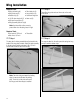
The recommended Center of Gravity (CG) location for
the Piper J-3 Cub is CG: 4
1
/
2
inches (114mm) back
from leading edge of wing at the root rib. Mark the
location of the CG onto the bottom of the wing using
a felt-tipped pen. Make sure the aircraft is upright when
checking the CG. If the nose of your aircraft hangs low,
add weight to the rear of the aircraft. If the tail hangs low,
add weight to the nose of the aircraft. Stick-on weights
are available at your local hobby store and work well for
this purpose. The CG range for your Piper J-3 Cub is
4–4
3
/
4
inches (102mm–120mm) back from the leading
edge of the wing at the root rib.
Check the Controls and Control Throws
Recommended Center of Gravity (CG)