Piper J-3 Cub Plug-N-Play ® Assembly manual Specifications Wingspan................................... 106 in (2692.5mm) Wing Area........................ 1630 sq in (10.52 sq dm) Length............................................. 68 in (1727mm) Weight........................ 14.5–16.5 lb (6.6 kg–7.
Table of Contents Using the Manual . . . . . . . . . . . . . . . . . . . . . . . . . . . . . . . . . . . . . . . . . . . . . . . . . . . . . . . . . . . . . . . . . . 3 Required Tools and Adhesives . . . . . . . . . . . . . . . . . . . . . . . . . . . . . . . . . . . . . . . . . . . . . . . . . . . . . . . . 3 UltraCote Covering Colors . . . . . . . . . . . . . . . . . . . . . . . . . . . . . . . . . . . . . . . . . . . . . . . . . . . . . . . . . . . 3 Before Starting Assembly . . . . . . . . . . . . . . .
Using the Manual This manual is divided into sections to help make assembly easier to understand, and to provide breaks between each major section. In addition, check boxes have been placed next to each step to keep track of each step completed. Steps with a single box () are performed once, while steps with two boxes ( ) indicate that the step will require repeating, such as for a right or left wing panel, two servos, etc. Remember to take your time and follow the directions.
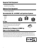
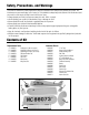
Required Field Equipment • Evolution Gas Start Kit EVO1002 • Ultra Manual Fuel Pump (HAN155) • AeroPeak AC/DC Charger (HAN9500) Optional Field Equipment • PowerPro™ 12V Starter (HAN161) • 12V 7aH Sealed Battery (HAN102) Recommended JR, JR SPORT and Spektrum Systems • XP9303 • XP7202 • XP6102 • XS600 • DX7 FS One Spektrum DX7 JR XP6102 JR XP9303 With FS One™ you get more than photorealistic fields, gorgeous . skies and realistic-looking aircraft. You get incredibly advanced .
Warranty Period Exclusive Warranty- Horizon Hobby, Inc., (Horizon) warranties that the Products purchased (the "Product") will be free from defects in materials and workmanship at the date of purchase by the Purchaser. Limited Warranty (a) This warranty is limited to the original Purchaser ("Purchaser") and is not transferable. REPAIR OR REPLACEMENT AS PROVIDED UNDER THIS WARRANTY IS THE EXCLUSIVE REMEDY OF THE PURCHASER. This warranty covers only those Products purchased from an authorized Horizon dealer.
Questions, Assistance, and Repairs Your local hobby store and/or place of purchase cannot provide warranty support or repair. Once assembly, setup or use of the Product has been started, you must contact Horizon directly. This will enable Horizon to better answer your questions and service you in the event that you may need any assistance. For questions or assistance, please direct your email to productsupport@horizonhobby.com, or call 877.504.0233 toll free to speak to a service technician.
Safety, Precautions, and Warnings This model is controlled by a radio signal that is subject to interference from many sources outside your control. This interference can cause momentary loss of control, so it is advisable to always keep a safe distance in all directions around your model, as this margin will help to avoid collisions or injury. • Always operate your model in an open area away from cars, traffic, or people. • Avoid operating your model in the street where injury or damage can occur.
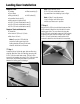
Landing Gear Installation Required Parts • Fuselage • Wheel assembly (2) • Cross brace • Wing strut tab (2) • 4-40 locknut (6) • Assembled shock strut (2) • Main gear strut (right and left) • 4-40 x 1/2-inch socket head screw (2) • 4-40 x 5/8-inch socket head screw (4) • 8-32 x 3/4-inch socket head screw (8) Required Tools and Adhesives • Threadlock • Hex wrench: 3/32-inch, 1/8-inch • Nut driver: 1/4-inch Note: Be sure the 6-32 bolts that secure the landing gear legs to the landing brackets are snug to mi
Stabilizer and Radio Installation Required Parts • Fuselage assembly • Stabilizer/elevator (2) 3 • 6 /8-inch (162mm) joiner • #6 washer (4) • Tail wheel assembly • 2-56 nut (4) • 4-40 locknut (3) • Large strut support bracket (2) • Small strut support bracket (2) • #6 x 5/8-inch sheet metal screws (2) • 4-40 x 5/8-inch socket head screw (3) • Support rod w/clevis, 10-inch (254mm) (2) • Support rod w/clevis, 9 1/2-inch (241mm) (2) • 6-32 x 3/4-inch socket head screw (4) Step 2 Slide the stabilizer into
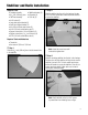
Stabilizer and Radio Installation Step 4 Step 6 Attach the tail wheel assembly to the fuselage using two #6 x 5/8-inch sheet metal screws. The forward screw goes through the gear and into the fuselage, while the rear screw goes through the two large strut support brackets, then through the gear and into the fuselage. Remove the clevis from each of the support rods. Use a hobby knife to clean the paint from the threads. Thread a 2-56 nut onto the threads, then replace the clevis.
Stabilizer and Radio Installation Step 8 Step 9 Clip the clevis to the strut support bracket. It will be necessary to adjust the position of the clevis to ensure the support rods are not causing any twists between the fuselage, stabilizer and fin. Tighten the nuts against the clevises once all adjustments have been made. Connect the clevises for the elevators to the elevator control horns. Step 10 Connect the clevises for the rudder to the rudder control horns.
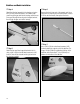
Stabilizer and Radio Installation Step 11 Step 14 Connect the rudder tiller bracket to the tailwheel steering arm using the two rudder springs. You will need to bend the springs to attach them on each end using pliers. Plug the throttle, rudder, and elevator servos into . the receiver. Note: A Y-harness is not included for the elevator servos. If you are not using a 6channel radio with the ability to mix the elevator servos together, you will need to purchase a reversing Y-harness (EXRA320).
Interior Detail Installation Required Parts • Fuselage assembly • Front seat • Rear seat • Hook and loop • Pilot • #2 x 1/2-inch sheet metal screw (4) Step 3 Use four #2 x 1/2-inch sheet metal screws to secure the floor into the fuselage. The floor will keep the seats from sliding in the fuselage. Required Tools and Adhesives • Phillips screwdriver Step 1 Plug the switch harness into the battery and receiver.
Wing Installation Required Parts • Wing (left and right) • Short strut pin (4) • Wing strut end (4) • Long strut pin (4) • Retainer clip (8) • Aluminum wing tube • 1/4-20 nylon wing bolt (2) • 4mm nut (4) • Mid-span cross brace (2) • Wing assembly (left and right) Step 2 Thread the wing strut ends and 4mm nuts on the ends . of the struts. Note: Use threadlock on the screws to prevent them from vibrating loose in flight.
Wing Installation Step 4 Step 6 Slide the aluminum wing tube into the fuselage. Then slide onto the wing tube. Plug the servo lead in the wing into the extension inside the fuselage. Confirm that there is a piece of tubing on the pin before inserting it into the brace. If not, install a piece of tubing to prevent vibration and radio interference. Slide the . short pins from the strut ends into the brace at the fuselage. It will be necessary to adjust the strut ends .
Check the Controls and Control Throws Check the operation of the control surfaces using the radio system. Make sure all the control surfaces are centered. If not, adjust the clevises as necessary, making sure to apply threadlock and tighten the locking nut against the clevises once the control surfaces have been centered. The amount of control throw should be adjusted as closely as possible using mechanical means, rather than making large changes electronically at the radio.
Pre-Flight Charge both the transmitter and receiver pack for your airplane. Use the recommended charger supplied with your particular radio system, following the instructions provided with the radio. In most cases, the radio should be charged the night before going out flying. All the batteries supplied with your Piper Cub are JR (Nicad) Extra packs. The receiver battery is 5-cell/6 volt 2400mah pack, replacement part number JRPB4470. The ignition battery is 4-cell/4.
2007 Official AMA National Model Aircraft Safety Code GENERAL 1. A model aircraft shall be defined as a non-humancarrying device capable of sustained flight in the atmosphere. It shall not exceed limitations established in this code and is intended to be used exclusively for recreational or competition activity. 2. The maximum takeoff weight of a model aircraft, including fuel, is 55 pounds, except for those flown under the AMA Experimental Aircraft Rules. 3.
2007 Official AMA National Model Aircraft Safety Code Radio Control 1. All model flying shall be conducted in a manner to avoid over flight of unprotected people. 2. I will have completed a successful radio equipment ground-range check before the first flight of a new or repaired model aircraft. 3. I will not fly my model aircraft in the presence of spectators until I become a proficient flier, unless I am assisted by an experienced pilot. 4.
© 2007 Horizon Hobby, Inc.. 4105 Fieldstone Road. Champaign, Illinois 61822. (877) 504-0233. horizonhobby.com hangar-9.