
User Manual

9
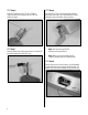
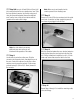
Step 910Use a pin drill and 5/64-inch (2mm) drill
bit to enlarge the outer hole of a standard servo arm. Slide
the brass pushrod connector into the hole and secure it
using the connector backplate. Remove the additional
arms from the horn so they will not interfere with the
operation of the water rudder linkage.
Note: Use side cutters to remove any
additional servo arms so they do not
interfere with the operation of the rudder.
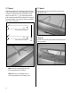
Step 11
Use the radio to center the rudder servo. Slide the
connector onto the pushrod wire, then attach the arm to
the servo. Center the rudder and use the 3mm x 6mm
machine screw to secure the pushrod. Cut the excess
pushrod leaving1/2–3/4-inch (13–19mm) forward of
the connector.
Note: Make sure to use threadlock on the
screw to prevent it from vibrating loose.
Step 12
Secure an 18-inch (457mm) servo extension to the rudder
servo lead. A connector has been supplied to prevent it
from becoming unplugged inside the float.
Step 13
With the connection between the servo lead and extension
inside the float, place the servo hatch onto the float. Use
a #1 Phillips screwdriver to install the four #2 x 1/2-inch
sheet metal screws that secure the hatch to the float.
Step 14
Repeat Steps 4 through 13 to install the remaining rudder,
servo and linkage.