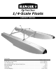
/4-Scale Floats Assembly manual Specifications Length.....................................................................................................................................47.625 in (1210mm) Overall Width of Float Assembly.................................................................................................27.25 in (692mm) Tip of Float to the Step................................................................................................................25.
Table of Contents Using the Manual . . . . . . . . . . . . . . . . . . . . . . . . . . . . . . . . . . . . . . . . . . . . . . . . . . . . . . . . . . . . . . . . . . 2 Required Tools and Adhesives . . . . . . . . . . . . . . . . . . . . . . . . . . . . . . . . . . . . . . . . . . . . . . . . . . . . . . . . 3 Before Starting Assembly . . . . . . . . . . . . . . . . . . . . . . . . . . . . . . . . . . . . . . . . . . . . . . . . . . . . . . . . . . . . 3 Recommended Accessories . . . . . . . . . . . . . . .
Required Tools and Adhesives Tools • Phillips screwdriver: #1 • Drill bit: 5/64-inch (2mm) • Hobby knife w/ #11 blade • Hobby knife • Painter's tape Adhesives • Silicone sealant • Medium CA • Pin drill • Silicone sealant • Adjustable wrench • Ball driver: 1/8-inch, 3/32-inch • Plastic wrap or waxed paper • Threadlock Before Starting Assembly Before beginning the assembly of your 25% Fiberglass Floats, remove each part from its bag for inspection. Closely inspect each piece for damage.
Warranty Period Exclusive Warranty- Horizon Hobby, Inc., (Horizon) warranties that the Products purchased (the "Product") will be free from defects in materials and workmanship at the date of purchase by the Purchaser. Limited Warranty (a) This warranty is limited to the original Purchaser ("Purchaser") and is not transferable. REPAIR OR REPLACEMENT AS PROVIDED UNDER THIS WARRANTY IS THE EXCLUSIVE REMEDY OF THE PURCHASER. This warranty covers only those Products purchased from an authorized Horizon dealer.
Questions, Assistance and Repairs Your local hobby store and/or place of purchase cannot provide warranty support or repair. Once assembly, setup or use of the Product has been started, you must contact Horizon directly. This will enable Horizon to better answer your questions and service you in the event that you may need any assistance. For questions or assistance, please direct your email to productsupport@horizonhobby.com, or call 877.504.0233 toll free to speak to a service technician.
Safety, Precautions and Warnings This model is controlled by a radio signal that is subject to interference from many sources outside your control. This interference can cause momentary loss of control so it is advisable to always keep a safe distance in all directions around your model, as this margin will help to avoid collisions or injury. • Always operate your model in an open area away from cars, traffic, or people. • Avoid operating your model in the street where injury or damage can occur.
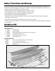
Float Assembly Required Parts • Float (right and left) • Servo hatch (2) • Strut bracket (4) • Rubber boot (2) • Servo (2) • 4-40 x 3/8-inch socket head bolt (2) • Rudder assembly (right and left) • Fuel tubing, 1/4-inch (6mm) (3) • 10 1/4-inch (260mm) front wire brace w/fittings (2) • 11-inch (280mm) rear wire brace w/fittings (2) • 19 1/4-inch (489mm) horizontal wire brace (2) • #2 x 1/2-inch sheet metal screw (8) • 8-32 x 1 1/4-inch socket head bolt w/shoulder (4) • 18-inch (457mm) servo extension (2)
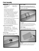
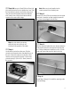
Step 6 Step 8 27 1/2-inch Insert the Z-bend from the (700mm) rudder pushrod into the rudder tiller arm from the bottom as shown. Step 7 Slide the rubber boot onto the pushrod wire. The boot will be pressed against the rudder tiller arm. Use two 4-40 x 1/2-inch socket head bolts to attach the rudder to the float. Use a small amount of silicone adhesive to secure the rubber boot to the float. Note: Use care not to get silicone adhesive on the pushrod wire.
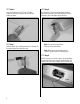
Step 910Use a pin drill and 5/64-inch (2mm) drill bit to enlarge the outer hole of a standard servo arm. Slide the brass pushrod connector into the hole and secure it using the connector backplate. Remove the additional arms from the horn so they will not interfere with the operation of the water rudder linkage. Note: Use side cutters to remove any additional servo arms so they do not interfere with the operation of the rudder. Step 11 Use the radio to center the rudder servo.
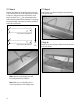
Step 14 Step 15 Slide the cross brace into the opening on the side of the float. Check that the holes in the float align with the brace, as there is a front and rear brace and the holes do not match. Use two 8-32 x 1 1/4-inch socket head machine bolts w/shoulder to attach the strut bracket. The screws go through the bracket, cross brace and into the preinstalled blind nuts inside the float. Install the rear cross brace following the same procedure as the previous step.
Step 17 Step 19 Remove the strut end fitting from one end of the preassembled 19 1/4-inch (489mm) wire braces. Slide a 1/4-inch (6mm) piece of fuel tubing onto the wire. The fuel tubing will be secured later in the manual. Use four 4-40 x 1/2-inch socket head screws to attach the wire braces between the cross braces. Once the wire braces are installed, go back and tighten the eight 8-32 x 1 1/4-inch socket head machine bolts w/shoulder.
Step 21 Step 22 Adjust the strut end fittings so the distance between the center of the screw heads will measure 11 3/16-inch (284mm) as shown. Use threadlock on the nuts and ends to prevent them from vibrating loose. The 4-40 nut is then tightened against the ends to keep them from rotating and vibrating loose as well. Prepare both braces at this time.
Step 23 Step 25 Remove the strut end fitting from one end of the preassembled 11-inch (280mm) wire braces. Slide a 1/4-inch (6mm) piece of fuel tubing onto the wire. The fuel tubing will be secured later in the manual. Use a 8-32 x 3/4-inch socket head bolt w/shoulder, 8-32 locknut and two #8 nylon washers to attach the 8 1/2-inch (216mm) rear diagonal strut to the strut bracket. Note that the front strut has a hole in one end which the diagonal brace will fit into when installed.
Step 26 Step 27 Thread a 4-40 nut onto the threaded end of the cross member. The distance from the center of the hole to the end of the nut is 15 1/8-inch (384mm). Attach the diagonal brace using a 4-40 x 3/8 socket head bolt. Leave the screw loose until the floats have been installed on the fuselage. Step 28 Thread a 4-40 locknut onto the diagonal brace. Only thread the nut on far enough to keep the diagonal attached to the front cross brace at this time.
Float Installation Required Parts • 8-32 x 3/4-inch socket head bolt standard thread (8) • 8-32 x 3/4- inch socket head bolt w/shoulder (4) • 8-32 x 3/4-inch socket head bolt from the original J-3 Cub kit(4) • Strut bracket (4) Required Tools and Adhesives • Ball driver: 1/8-inch • Adjustable wrench • Hobby knife • Medium CA • Threadlock Step 1 Remove the landing gear from the fuselage. Use a hobby knife to remove the covering over the bolt holes to expose the blind nuts at the rear of the fuselage.
Step 4 Step 5 With the fuselage inverted, use two 8-32 x 3/4-inch socket head bolts, four nylon washers and two 8-32 locknuts to attach the front bracing to the float mounting brackets on the fuselage. The bracing and washers are installed in the same fashion at the fuselage as they are at the float. Slide the tubing so it is at the inersection of the two wires to prevent them from rubbing and causing radio interference. Apply medium CA to secure the position of the fuel tubing.
Step 6 Plug the lead from the float servo extension into the end of the Y-harness that has been mounted in the side of the fuselage. Use tie wraps to secure the extension to the front diagonal brace to prevent it from becoming damaged if it is left loose to flap freely in the breeze. Step 7 Now that the floats are installed, go back and make sure all the hardware has been tightened. Slide any extra servo extension lead into the float.
2008 Official AMA National Model Aircraft Safety Code GENERAL 1. A model aircraft shall be defined as a non-humancarrying device capable of sustained flight in the atmosphere. It shall not exceed limitations established in this code and is intended to be used exclusively for recreational or competition activity. 2. The maximum takeoff weight of a model aircraft, including fuel, is 55 pounds, except for those flown under the AMA Experimental Aircraft Rules. 3.
2008 Official AMA National Model Aircraft Safety Code Radio Control 1. All model flying shall be conducted in a manner to avoid over flight of unprotected people. 2. I will have completed a successful radio equipment ground-range check before the first flight of a new or repaired model aircraft. 3. I will not fly my model aircraft in the presence of spectators until I become a proficient flier, unless I am assisted by an experienced pilot. 4.
Instructions for Disposal of WEEE by Users in the European Union This product must not be disposed of with other waste. Instead, it is the user’s responsibility to dispose of their waste equipment by handing it over to a designated collection point for the recycling of waste electrical and electronic equipment.