Copyright Notice Copyright © 2005-2015 Handlink Technologies Inc. All rights reserved. No part of this document may be copied, reproduced, or transmitted by any means, for any purpose without prior written permission. Protected by TW patent 223184, JPN patent 3099924 and China patent ZL 03 2 04640.5.
Table of Contents 1 Introduction ----------------------------------------------------------------------------------------------------------------- 4 1-1 Package Contents -------------------------------------------------------------------------------------------------------- 4 1-2 Features --------------------------------------------------------------------------------------------------------------------- 5 1-3 Precautions ------------------------------------------------------------------------------------
-2-4 GUEST SETTING ---------------------------------------------------------------------------------------------55 3-2-4-1 Guest ESSID Settings ------------------------------------------------------------------------- 55 3-2-4-2 Authentication ------------------------------------------------------------------------------------ 57 3-2-4-3 Usage Time --------------------------------------------------------------------------------------- 59 3-2-4-4 Customization --------------------------------------
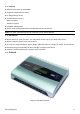
1 Introduction The GW-1 guestWiFi account generator is designed as 300Mbps high speed wireless gateway for enterprises and schools to provide guests a secure Wi-Fi network in their meeting room, guest lobby, and library. It is deployed by MIS simply as adopting IP Plug and Play technology, all a guest has to do is to generate a guest account with a single click, and with a press of a button the guest ID will be shown on the display instantly.
1-2 Features z Wireless data rates up to 300Mbps z Supports 20Simultaneous Users z IP Plug and Play (iPnP) z Comprehensive security WPA encryption WPA2 Encryption z Intelligent Management z Built-in AAA (Authentication/Accounting/Authorization) mechanism Note: The "PnP" Function only can be used with TCP/IP-based Network. 1-3 Precautions z Never remove or open the cover. You may suffer serious injury if you touch these parts. z Never install the system in the wet locations.
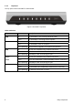
1-4-1 Top Panel The top panel of the GuestWiFi is shown below. Figure 2 GuestWiFi Top Panel LEDs Indication LED State Description PWR Off The GuestWiFi is not receiving electrical power. Green The GuestWiFi is receiving electrical power. Off The GuestWiFi status is defective. Green The GuestWiFi status is complete. SYS Green (Blinking) During firmware upgrades, this system LED will blink. WAN Off Port has not established any network connection.
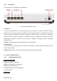
1-4-2 Rear Panel The rear panel of the GuestWiFi is shown below. Figure 3 GuestWiFi Rear Panel 1. LAN (1-4): The rear panel supports four auto-sensing RJ-45 ports and all ports can be auto-switched to MDI-II connections. The LAN ports used for linking hosts or other network devices. The individual port can be either connected to 100BaseTX networks or 10BaseT networks. When connecting to a 100BaseTX network, the ports operate at 100Mbps in half-duplex mode or 200Mbps in full-duplex mode.
Four LAN Ports (10BaseT/100BaseTX Auto cross-over) One WAN Port (10BaseT/100BaseTX Auto cross-over) Encryption WPA (Wi-Fi Protected Access) WPA2 (Wi-Fi Protected Access) LED Indicators One POWER LED One WAN 10/100M Link/Activity LED Four LAN 10M/100M Link/Activity LEDs One Wireless Link/Activity LED One System LED Power Requirement External Power Adapter Input: 100-240 VAC, 50/60 Hz Output: 12V, 1.
1-5-2 Software Specifications Networking • IEEE802.3u 10BaseTx Ethernet • IEEE802.3u 100BaseTX Fast Ethernet • IEEE802.11b Wireless LAN • IEEE802.11g Wireless LAN • IEEE802.
Security and Firewall • Layer 2 Isolation Security • SSL User Login page/ Configuration Page • SSL Administration • VPN Pass through (IPSec/PPTP) • Customize SSL Certificate • Pass Through IP/MAC/URL Address • Restricted Destination Filtering IP/URL • VPN (IPSec/PPTP) Pass through • PPTP VPN Client • WPA • WPA2 Management • Web-based Management Tool • Firmware Upgrade via HTTP/TFTP • Wizard setup for step-by-step Configuration • Backup/Restore/Factory Default Setting • Remote
2 Installation The followings are instructions for setting up the GuestWiFi. Refer to the illustration and follow the simple steps below to quickly install your GuestWiFi. Wall-Mounting The GuestWiFi can be wall-mounted on a wall by applying the two mounting brackets on screws. Figure 4 Wall-Mounting Bracket - Bottom of GuestWiFi Please refer to the following instructions for mounting a GuestWiFi on a wall or other surface. 1. Install two screws on a wall according to the relative positions shown below.
2-1 Installation Requirements Before installing the GuestWiFi, make sure your network meets the following requirements. System Requirements The GuestWiFi requires one of the following types of software: z Windows 98 Second Edition/NT/2000/XP/Vista/7 z Red Hat Linux 7.3 or later version z MAC OS X 10.2.4 or later version z Any TCP/IP-enabled systems like Mac OS and UNIX (TCP/IP protocol installed) z Standard phone line for xDSL modem Or Coaxial cable for Cable modem z Web Browser Software (Microsoft I.E 5.
ISP Requirements Verify whether your ISP use fixed or dynamic IP. If it is a fixed IP, be sure to get the IP from your ISP. For dynamic IP, which is mostly used, the PC will get the IP automatically whenever it hooks up on the modem.
2-2 Getting Start 1. Connect the Ethernet cable to the guestWiFi’s LAN port. 2. Ensure that your modem and computer are both switched on. 3. Use the supplied cable to connect the guestWiFi 's WAN port to the modem. Check that the Cable/xDSL Status LED lights. 4. Connect your computer to one of the 10/100 LAN ports on the guestWiFi. Check that the LAN Port Status LED lights. 5. 14 Configure the further parameters via a Web browser.
3 Configuring the GuestWiFi 3-1 Setting Wizard Step 1: Start your browser, and then enter the factory default IP address 10.59.1.1 in your browser’s location box. Press Enter. Figure 6 Web Browser Location Field (Factory Default) Step 2: The GuestWiFi configuration tools menu will appear. In the Username and Password field, type the factory default user name admin and password admin and click Login. If you are first time setting the system, the wizard setup screen will appear.
Figure 9 System Quick View Click on reset button to clear the username and password data. Note: ) This Web agent is best viewed with IE 5.0 or Netscape 6.0 and above browsers. ) If you would like to change the password please see Step 10. ) Username and Password can consist of up to 20 alphanumeric characters and are case sensitive.
Step 3: Internet Connection Setting Select the appropriate Internet connection type to connect to your ISP. Figure 10 Internet Connection Setting Screen z DHCP Client The device can work as a DHCP client. This allows the device to obtain the IP address and other TCP/IP settings from your ISP. If your xDSL/Cable comes with this feature, please enable Use DHCP Client.
z Static IP Setting If Static IP Setting is selected, then this screen will appear. Enter the IP address information provided by your ISP. Figure 12 Internet Connection Setting Screen—Static IP Setting Item Default Description IP Address 0.0.0.0 Enter the IP address provided by your ISP. Subnet Mask 0.0.0.0 Enter the subnet mask for the IP address. Gateway IP 0.0.0.0 Enter the Gateway IP Address provided by your ISP.
z PPPoE (Point-to-Point Protocol over Ethernet) If “PPPoE” is selected, then this screen will appear. Enter the username, password and other major fields. Figure 13 Internet Connection Setting Screen—PPPoE Setting Item Default Username Empty Password Empty PPP MTU Setting 1492 TCP MSS Setting 1452 Service Name Empty Easy Hotspot Kit Description Enter the user name provided by your ISP. The user name can consist of up to 80 alphanumeric characters and is case sensitive.
Item Default Description Connect on Demand and Max Idle Time Connect on Demand Enable You can configure your GuestWiFi to cut your connection with your ISP after a specified period of time (Max Idle Time). If you have been disconnected due to inactivity, Connect on Demand enables your GuestWiFi to automatically re-establish your connection as soon as you Max Idle Time 10 attempt to access the Internet again. If you wish to activate Connect on Minutes Demand, click the radio button.
z PPTP Client (Point-to-Point Tunneling Protocol) If “PPTP” is selected, then this screen will appear. Fill out all the information provided by your ISP. Figure 14 Internet Connection Setting Screen—PPTP Client Setting Item Default My IP Address Empty My Subnet Mask Empty Easy Hotspot Kit Description Enter the PPTP local IP address provided by your ISP. Enter the PPTP local Subnet Mask IP address for the IP address (My IP Address).
Item Gateway IP Address Default Empty PPTP Server IP Address Empty Description Enter the PPTP server Gateway IP address provided by your ISP. Enter the PPTP server IP address provided by your ISP. Enter the user name provided by your ISP. The user name Username Empty can consist of up to 80 alphanumeric characters and is case sensitive. Password Empty Enter the user password provided by your ISP. The password can consist of up to 80 alphanumeric characters and is case sensitive.
Step 4: Wireless Setting This page allows you to define ESSID, Channel ID and WEP/WPA encryption for wireless connection. Figure 15 Wireless Setting Screen Item Default Description Country ETSI Select the Country code of the dropdown list. Channel 6 Enter the channel ID for wireless connection.
Step 5: System Setting Figure 16 System Setting Screen 24 Easy Hotspot Kit
Item Default Description Username admin Enter the user name. The user name can consist of up to Password admin Enter the user password. The password can consist of up Confirm Empty 80alphanumeric characters and is case sensitive. to 80 alphanumeric characters and is case sensitive. Enter the password of administrator for confirmation. NTP Setting Server IP/Domain Name Empty Enter the IP address/domain name of NTP server. The maximum allowed characters length is 100.
3-2 Advanced Setup The Advanced Setting enables you to configure advanced settings related to accessing the Internet, including, 1. MANAGEMENT 2. 3. SESSION TRACE BANDWIDTH SNMP SECURITY PASS THROUGH SECURE REMOTE SYSTEM 4. 5.
3-2-1 MANAGEMENT 3-2-3-1 Syslog The function allows the device to transmit event messages to your syslog server or your email address for monitoring and troubleshooting. z Syslog Setting Figure 18 Syslog Setting Screen Item Syslog Default Description Disable Enables or disables the syslog server function. Empty Enter syslog server’s IP address. The GuestWiFi will send all of Syslog on LAN Server IP Address its logs to the specified syslog server.
Item Default Description Syslog on WAN Server 1 IP Address Empty Enter IP address of first syslog server. Server 2 IP Address Empty Enter IP address of second syslog server. Send to Email Disable Enables or disables the send to e-mail function. E-mail Server IP Address or Domain Empty Name Enter the SMTP server IP address or domain name. The maximum allowed characters length is 50. SMTP Port 25 The SMTP port allowed range is 25 or 2500 to 2599.
z Log Categories Figure 20 Log Settings Screen Easy Hotspot Kit 29
Item Interval Time Description System System Information 5~60 minutes The log included system information would be sent according to specified interval time. Format: PRODUCT=GW-1;VER=2.00.00;LOGNAME=DVI; DATE=07Mar26;TIME=11:30:00; WANMAC=09-00-0e-00-00-01;LANMAC=09-00-0e-00-00-02; WLANMAC=09-00-0e-00-00-03; IP_ADDRESS=210.66.37.
Firmware Update When firmware A log will be sent if firmware update completed Notice update completed Format: PRODUCT=GW-1;VER=2.00.00;LOGNAME=FUN; DATE=07Mar26;TIME=15:23:32; WANMAC=09-00-0e-00-00-01;LANMAC=09-00-0e-00-00-02; WLANMAC=09-00-0e-00-00-03; IP_ADDRESS=210.66.37.21; MESSAGE=Success;OLD_FRIMWARE=v1.00.01; NEW_FIRMWARE=v1.00.02 Message = Success | Fail User User Login When user A log including users information will be sent when user logged-in logged –in Format: PRODUCT=GW-1;VER=2.00.
ACCOUNT_PRICE= USD20.00; ACCOUNT_USAGE_TIME=10:59:59; Click Apply button to save the new settings. Click Apply button, the success dialog box appears. Click on Back to return to Logs setting screen.
3-2-3-2 Session Trace Session Trace is an intelligent function to help service provider to trace every user’s access behavior. When “session trace” is enable , the system will collect information such like destination IP, destination port, source IP, source MAC, source port by every user and send the collected information in text format file to specified TFTP server or Email Server.
Item Send to Email Default Disable Description Enables or disables the send to e-mail function. E-mail Server IP Address or Domain Empty Enter the SMTP server IP address or domain name. The Name maximum allowed characters length is 50. SMTP Port Empty The SMTP port allowed range is 25 or 2500 to 2599. E-mail (SMTP) Server Disable If your SMTP server requires authentication before accepting needs to check my e-mail, click on check box.
3-2-3-3 Bandwidth The function enables administrator to limit bandwidth usage on a per user basis (MAC address). That prevents users from consuming a disproportionately large amount of bandwidth so every user gets a fair share of the available bandwidth. Figure 23 Item Default Bandwidth Setting Screen Description Bandwidth Disable Enables or disables Bandwidth Management. Maximum Upstream 64Kbps Specify the amount of upstream bandwidth.
3-2-3-4 SNMP The SNMP Agent Configuration screen enables you to access to your device via Simple Network Management Protocol. If you are not familiar with SNMP, please consult your Network Administrator or consult SNMP reference material. You must first enable SNMP on the SNMP Agent Configuration screen. Figure 24 SNMP Setting Screen Item Default Description SNMP Disable Disables or enables the SNMP management.
Item Privileges Default Read/Write Description Choose “Read”, “Write”, “Trap Recipients” and “All” for different privileges. The default setting of the entry 2 is “write” and others are “read”. Status Valid/Invalid Chosen “Valid” or “Invalid”. The default setting of entry 1, 2 are valid and others are invalid.
3-2-2 SECURITY 3-2-2-1 Pass Through This function allow administrator to set some special devices pass through the GuestWiFi system. Because some network devices might be constructed under the GuestWiFi. However these devices needn’t be checked and authorized. The GuestWiFi provides a pass through list and the administrator can control which devices can be pass through with authentication.
Item Default Description Pass Through Disable Enables or disables the pass through function. Destination URL/IP Address Pass Through URL or Website Empty Enter the URL Page; please use this format such like “http://www.yahoo.com”. The maximum character of the URL Page is 50. Start IP Address Empty Enter the start IP address of you wants pass through. End IP Address Empty Enter the end IP address of you wants pass through.
3-2-2-2 Secure Remote This feature allows you to create a secure connection to a remote site or back end system with VPN PPTP Client. If “Secure Remote” is enabled, the RADIUS packet/ syslog will be transferred to this secure connection. Figure 26 Secure Remote Setting Screen Item Auto-connect at Default Disable Start-up (Always Description Enable the check box to automatically establish the PPTP connection. connect) PPTP Server IP Empty Enter the PPTP server IP address provided by your ISP.
3-2-3 SYSTEM 3-2-3-1 System Define the GuestWiFi System configuration.
Figure 28 System Setting Screen Item Default Description The system name can consist of up to 40 System/Host Name Empty Domain Name Empty Location Information Empty Enter your location information. System The system date of the GuestWiFi. The valid setting of Date year is from 2002 to 2035. alphanumeric characters. The Domain name can consist of up to 80 alphanumeric characters.
Item Default Description Enables or disables NTP (Network Time Protocol) Time Server. Network Time Protocol can be utilized to NTP Setting Disable synchronize the time on devices across a network. A NTP Time Server is utilized to obtain the correct time from a time source and adjust the local time. Enter the IP address/domain name of NTP server. The Server IP/Domain Name Empty Time Zone GMT-12:00 Select the appropriate time zone for your location.
Item Default Description Option: default or customize certificate, These are two ways to create a certificate, one is purchase a SSL Certificate Default certificate from a certificate authority (Ex. Verisign or Thawte), and another is creating a self-certificate (For example: Uses OpenSSL tool). Click Apply button to save the new settings. Click Apply button, then Restart dialog box will appear. Click Apply to restart the system.
Figure 31 Restart Dialog Box z Device IP (LAN IP) Setting Figure 32 Device IP (LAN IP) Setting Item Default IP Address 10.59.1.1 Description The internal LAN IP address of your Wireless Subscriber Server Gateway. Subnet Mask z 255.0.0.0 Enter the subnet mask for the IP address. WAN MAC Address Figure 33 WAN MAC Address Setting Item IP Address z Description The default MAC address is set to the WAN physical interface on device.
DHCP Client The device can work as a DHCP client. This allows the device to obtain the IP address and other TCP/IP settings from your ISP. If your xDSL/Cable comes with this feature, please enable Use DHCP Client. Figure 35 DHCP Client Setting Screen Static IP Figure 36 Static IP Setting Screen Item Description IP Address Enter the IP address for the xDSL/Cable connection (provided by your Subnet Mask Enter the subnet mask for the IP address. ISP).
PPPoE Figure 37 PPPoE Setting Screen Item Default Description User Name Empty Enter your PPPoE account name. The user name can consist Password Empty Enter your PPPoE password. The password can consist of PPP MTU Setting 1492 MTU (Maximum Transfer Unit) specifies maximum of up to 80 alphanumeric characters and is case sensitive. up to 80 alphanumeric characters and is case sensitive. transmission unit size. TCP MSS Setting 1452 MSS (Maximum Segment Size) specifies maximum segment size.
Item Service Name Default Empty Description Enter the service name provided by your ISP. The service name can consist of up to 64 alphanumeric characters and is case sensitive. Connect on Demand and Max Idle Time Connect on Demand Enable You can configure your GuestWiFi to cut your connection Max Idle Time with your ISP after a specified period of time (Max Idle Time).
PPTP Figure 38 PPTP Setting Screen Item My IP Address Default Empty Description A PPTP local IP address for the xDSL/Cable connection (provided by your ISP). My Subnet Mask Empty Enter the PPTP local IP address for the xDSL/Cable connection. Gateway IP Address Empty A PPTP local default gateway for the xDSL/Cable connection (provided by your ISP). PPTP Server IP Address Empty Username Empty Enter the PPTP server IP address for the xDSL/Cable connection (provided by your ISP).
Item Password Default Empty Description Enter your PPTP password. The password can consist of up to 80 alphanumeric characters and is case sensitive. PPP MTU Setting 1460 MTU (Maximum Transfer Unit) specifies maximum transmission unit size. TCP MSS Setting 1400 MSS (Maximum Segment Size) specifies maximum segment size. Connection ID/Name Empty Enter the connection ID or connection name. The connection ID/Name can consist of up to 81 alphanumeric characters and is case sensitive.
3-2-3-3 Server Figure 39 Server Setting Screen Item Default Description Web Server Enter the HTTP port number. The HTTP port allowed HTTP Port 80 range is 80 or 8010 to 8060. For access the GuestWiFi system under NAT, please tab the “http://HTTP Port IP Address: Port Number”. Enter the HTTPS port number. The HTTPS port allowed HTTPS Port 443 range is 443 or 4430 to 4440. For access the GuestWiFi system, please tab the “https://HTTPS Port IP Address: Port Number”.
Item Default Description There are three types of DHCP Services. DHCP Server Enable DHCP Disable—Disable the DHCP server function. DHCP Relay—Enable DHCP Relay function. DHCP Server—Enable DHCP server function. DHCP Relay DHCP Server IP Address DHCP Server DHCP Pool Starting Address Pool Size Lease Time To route DHCP through an external server, the administrator needs to enable the DHCP relay and assign a valid DHCP server IP address. Empty Enter the IP address of DHCP server.
Static DHCP This function allows subscriber to assign IP address on the LAN to specific individual computers based on their MAC Address. Figure 40 Server Setting Screen Item Default IP Address Empty Description Enter the IP address that subscriber want to assign to the computer on LAN with the MAC address the subscriber will also specify MAC Address Empty Enter the MAC address of a computer on your LAN Click Apply button to save the new settings.
3-2-3-4 Wireless Figure 41 Wireless Setting Screen Item Default Description General Settings Country ESTI Channel 6 802.11 mode Select the channel ID for wireless connection. 802.11n+802.1 1g+802.11b Channel width Auto 20/40MHz Beacon Interval 200 This value valid range is 1 to 1000 indicates the frequency interval of the beacon. This value valid range is 256-2342.
Click Apply button to save the new settings. Click Apply button, the restart dialog box appears. Click on Apply to restart the system. Figure 42 Restart Dialog Box This operation will load the default manufacturer configuration to the system. All this page (Wireless) configuration setup will be replaced by default settings.
Item Default Description General Settings Active Active or inactive the wireless connection interface. ESSID Guest The ESSID is the unique name that is shared among all points in a wireless network. It is case sensitive and must not exceed 32 characters. Select disable to allow wireless station to communicate with Security Enable the device without any data encryption. Select enable to enable WPA or WPA2 data encryption.
3-2-4-2 Authentication Figure 44 Authentication Setting Screen Item Authentication Type Default Description No Option: No Authentication, Built-in Authentication or User Authentication Agreement. No Authentication― Subscriber can direct access the Internet without enter username and password. Built-in Authentication― Wireless Subscriber Gateway provides “Built-in Authentication” for service provider to build up an Internet service without any extra authentication software.
Item Current User Default 1 Min(s) Information Backup Description The system provides automatically backup account information and unused account to flash ROM. This function allow administrator to adjust the backup time. The default value is 1 minute. The Current User Information Backup valid range is 1 to 1440. Redirect Login Page Empty URL The input format can be http://www.yahoo.com. The maximum character of the URL Link is 200.
3-2-4-3 Usage Time This function allow service provider to generate the subscriber accounts. Figure 46 Accounting Setting Screen Item Default Description Expiration Un-used account will be deleted after ~hours 12 hours Enter the number of hours/days. The field maximum value is 30 hours/ days. automatically Usage Time The duration of the 3 hours period. When this period Enter the number of hours/days. The field maximum value is 30 hours/ days. expired, user account will be discontinued.
3-2-4-4 Customization z Login Page The guestWiFi provides three different login page formats, including standard, redirect, advanced and frame format. Standard For some service providers, they may hope to have a customize subscriber’s login page to the users. This function helps them to realize the ideal. The page elements are including login page title, background color, subtitle etc.
Item Copyright Default Description Enable The copyright is allowed the administrator to input a paragraph in the subscriber login page for copyright information. The maximum character of the copyright is 80. Background Color FFFFFF The background text color can be specified color. For the specified text color format please views the color grid. The allowed format is Hexadecimal. Figure 48 Login Page Screen Before you add logo to the login page, please make sure the logo image file is defined.
Redirect This allow service provider to redirect the subscriber’s browser to a specified home page. Figure 50 Redirect Login Page Setting Screen Copy and paste the following HTML Code into your home page to produce redirect subscriber login page.
Advanced This function allow user to design login page of Wireless Subscriber Gateway. Figure 52 Advanced Login Page Setting Screen Item Default Description Welcome Slogan Welcome The maximum allowed characters length is 80. Page Background None The page background can be none or specified color. For the background color format please views the color grid. The allowed format is Hexadecimal.
Figure 53 Color Gird Frame If “Frame” is selected the subscriber login page will be separate into Top Frame and Bottom Frame. Bottom Frame is a default format for username and password input, Top Frame is allowed to be specified a URL to link. www.caesarpark.com Figure 54 Frame Login Page Setting Screen Item Default Top Frame URL Link Empty Description The input format can be http://www.yahoo.com. The maximum character of the URL Link is 200.
Figure 55 Example-Login Page Screen z Logo This function allows service provider to upload the customer’s logo image file which can be shown on the standard login page and account printout of PC-connected printer.
Figure 57 Login Page Item File Path Default Empty Description Enter the file pathname of the logo file in the File Path field. Click Apply button to save the logo file to system. Click Delete button to delete the logo file.
Information Window This function allow service provider can decide whether they want an “Information Window” pop-up on subscriber PC when authenticate successful or not and specified text of information window. Subscriber can type “http://1.1.1.1/info” to open the information window again or enter “http://1.1.1.1/logout” to logout immediately if accumulation billing selected.
Figure 59 Example-information windows Screen 68 Easy Hotspot Kit
User Agreement Page This function allow user to design user agreement page of Internet Subscriber Server.
3-2-5 EMPLOYEE ESSID SETTINGS Figure 62 Employee ESSID Setting Screen Item Default Description General Settings Active Active or inactive the wireless connection interface. ESSID Guest The ESSID is the unique name that is shared among all points in a wireless network. It is case sensitive and must not exceed 32 characters. Select disable to allow wireless station to communicate with Security Enable the device without any data encryption. Select enable to enable WPA or WPA2 data encryption.
3-3 System Status Display GuestWiFi system basic status, including, 1. System 2. Account List 3. Account Log 4. Current User 5. DHCP Clients 6.
3-3-1 System The System Information Menu displays current system basic information including the service connection message, host name, LAN, WAN, DHCP Configuration, DNS, SSL Certificate, network traffic Information and the system firmware version number.
Figure 65 System Status Screen Easy Hotspot Kit 73
3-3-2 Account List You can display a list of all the account information on this device. This table includes the username, password, usage time, time created, login time, expiration time and status. Figure 66 Account List Click on refresh button to update the account list page. Click the column button to sort the column in ascending/descending order. Select the check boxes and click ‘Delete’ to delete the accounts. Delete all accounts in account list.
3-3-3 Account Log The account log shows the accounts’ log information. Figure 67 Account Log This allow you to export the account logs to a text file format. (export.log) Click on Clear Log to remove all account log entries. Click on refresh button to update the account log page. Click the column button to sort the column in ascending/descending order.
3-3-4 Current User Display the current logged-in subscribers’ status. It allow service provider to disconnect any subscribers. Figure 68 Current User List Figure 69 Current User List (No Authentication) Click on refresh button to update the current user list page. Type Username IP Address MAC Address Click the column button to sort the column in ascending/descending order. Select the check boxes and click ‘Disconnect’ to disconnect accounts. Disconnect all accounts in current user list.
3-3-5 DHCP Clients The DHCP client table shows the current DHCP users on the LAN. Figure 70 Current User Screen 3-3-6 Session List The remote site administrator could monitor the real time usage status of GuestWiFi via this page.
3-4 System Tools This allows service provider or administrator to process Firmware upgrade, change password and backup or restore configuration. 1. Configuration 2. Firmware 3. Boot Code 4. System Account 5. SSL Certificate 6. Ping Command 7. Restart 8.
3-4-1 Configuration Use the Configuration item to save, restore or reset configuration parameters of the GuestWiFi. Figure 73 Configuration Setting Screen Item Backup Default Description Click it to save the system configuration to your computer. (export.cfg) Remote TFTP Server IP Empty Enter the IP address of TFTP Server. Address File Name Empty Enter the file name in the File Name field. Restore Click it to restore your system configuration.
3-4-2 Firmware Upgrade The Firmware Upgrade menu loads updated firmware to be permanent in flash ROM. The download file should be a binary file from factory; otherwise the agent will not accept it. After downloading the new firmware, the agent will automatically restart it. z Manual Firmware Upgrade Figure 74 Manual Firmware Upgrade Setting Screen Item Default Description This allow administrator to upgrade the firmware via HTTP.
z Scheduled Firmware Upgrade Scheduled Firmware Upgrade is a program that enables an automatic upgrade to the latest firmware version through the TFTP server. Figure 75 Scheduled Firmware Upgrade Setting Screen Item Default Description Disable/Enable Disables or enables the scheduled firmware upgrade function. TFTP Server IP Empty Enter the IP address of TFTP Server. File Synchronization Empty Enter the file name and location in the File Synchronization field.
3-4-3 Boot Code Figure 77 Boot Code Upgrade Setting Screen 3-4-4 System Account Use the System Account screen to change the system accounts.
Item Description Username The username can consist of up to 20 alphanumeric characters and is sensitive. Password The password can consist of up to 20 alphanumeric characters and is sensitive. Confirm The password for confirmation. z Administrator Account Step 1: Start your Web browser and enter the factory default IP address 10.59.1.1 in your browser’s location box. Press Enter. Figure 79 Web Browser Location Field (Factory Default) Step 2: The GuestWiFi configuration main menu will appear.
Figure 81 System Quick View 3-4-5 SSL Certificate The function allows you to download the registered CA certificate into the GuestWiFi. Figure 82 SSL Certificate Download Setting Screen Note: The password field must the same as the CA’s registered password.
3-4-6 Pin Command The Ping function can check the GuestWiFi networking connective or not. Figure 83 Ping Command Screen Item IP or URL Easy Hotspot Kit Description Enter the IP address or the URL link.
3-4-7 Restart If your GuestWiFi is not operating correctly, you can choose this option to display the restart GuestWiFi screen. Clicking the apply button restart the GuestWiFi, with all of your settings remaining intact. Figure 84 Restart Screen 3-4-8 Logout If you would like to leave the configuration page, please click apply to exit.
Appendix A Signal Connection Arrangements RJ-45 Ethernet Port The GuestWiFi RJ-45 Ethernet port can connect to any networking devices that use a standard LAN interface, such as a Hub/Switch Hub or Router. Use unshielded twisted-pair (UTP) or shield twisted-pair (STP) cable to connect the networking device to the RJ-45 Ethernet port. Depending on the type of connection, 10Mbps or 100Mbps, use the following Ethernet cable, as prescribed. 10Mbps: Use EIA/TIA-568-100-Category 3, 4 or 5 cable.
Appendix B Regulations/EMI Compliance FCC Statememt Federal Communication Commission Interference Statement This equipment has been tested and found to comply with the limits for a Class B digital device, pursuant to Part 15 of the FCC Rules. These limits are designed to provide reasonable protection against harmful interference in a residential installation.
LIMITED WARRANTY GuestWiFi What the warranty covers: We warrant its products to be free from defects in material and workmanship during the warranty period. If a product proves to be defective in material or workmanship during the warranty period, we will at its sole option repair or replace the product with a like product with a like product. Replacement product or parts may include remanufactured or refurbished parts or components.