Dolphin® 7900 Series Microsoft® Windows Mobile™ 2003 Second Edition Software for Pocket PCs User’s Guide
Disclaimer Hand Held Products, Inc. (“Hand Held Products”) reserves the right to make changes in specifications and other information contained in this document without prior notice, and the reader should in all cases consult Hand Held Products to determine whether any such changes have been made. The information in this publication does not represent a commitment on the part of Hand Held Products.
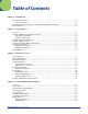
Table of Contents Chapter 1 - Introduction Required Safety Labels ....................................................................................................................... 1-2 Laser Safety Label ........................................................................................................................ 1-2 Regulatory and Safety Approvals for all Dolphin 7900 Series Terminals ......................................... 1-3 FCC Compliance................................................
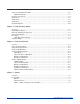
Using the Soft Input Panel (SIP) .........................................................................................................4-6 Input Panel Options.......................................................................................................................4-7 Drawing on the Screen ........................................................................................................................4-8 Status Icons......................................................................
System Tab ..........................................................................................................................................7-7 About.............................................................................................................................................7-7 Backlight .......................................................................................................................................7-7 Certificates ...............................................
802.11b Settings ..................................................................................................................................9-2 Status Icons ...................................................................................................................................9-2 Status Tab......................................................................................................................................9-3 Config Tab ......................................................
Using the Dialler................................................................................................................................11-5 Making a Call..............................................................................................................................11-5 Receiving a Call ..........................................................................................................................11-6 Ending a Call.............................................................
Dolphin Mobile Base Hardware Overview .......................................................................................14-2 Front Panel ..................................................................................................................................14-2 Bottom Panel...............................................................................................................................14-3 Back Panel.................................................................................
1 Introduction Overview Congratulations on the purchase of the Dolphin 7900 mobile computer! You have made a wise choice in selecting the Dolphin, a device known worldwide for its ergonomic form factor, light-weight, rugged design and single-handed data collection capabilities. Ergonomics The patented shape of the Dolphin 7900 fits into either hand comfortably with major function keys that are easy to access.
Required Safety Labels Dolphin 7900 mobile computers meet or exceed the requirements of all applicable standards organizations for safe operation. However, as with any electrical equipment, the best way to ensure safe operation is to operate them according to the agency guidelines that follow. Please read these guidelines carefully before using your Dolphin mobile computer.
Regulatory and Safety Approvals for all Dolphin 7900 Series Terminals Parameter Specification U.S.A Canada European Community FCC Part 15, Class B ICES-003 EN 55022 (CISPR 22) Class B EN60950 EN60825-1 EN55024:1998 The CE Mark on the product indicates that the system has been tested to and conforms with the provisions noted within the 89/336/EEC Electromagnetic Compatibility Directive and the 73/23/EEC Low Voltage Directive. For further information, please contact: Hand Held Products, Inc.
802.11b and Bluetooth The required safety label that appears on the back of Dolphin 7900 terminals equipped with an 802.11b and a Bluetooth radio combination is as follows: F O R H O M E O R O F F I C E US E Tested to Comply With FCC Standards T h i s C l as s B Di gi t al appar at u s c o mpl i e s w i t h C a n a d i a n I C E S - 0 0 3 . C e t ap p ar i e l n u m e r i q u e de l a Classe B est c onforme a la norme NMB -003 du Canada. www.handheld.com Hand Held Products, Inc.
FCC Compliance Dolphin mobile computers meet or exceed all applicable standards and have been manufactured to the highest level of quality. Dolphin 7900 Series Batch Terminal Dolphin 7900 Series Batch terminals comply with part 15 of the FCC rules. Operation is subject to the following two conditions: (1) this device may not cause harmful interference, and (2) this device must accept any interference received, including interference that may cause undesired operation.
RF, Regulatory, and Safety Agency Approvals for 802.11b and Bluetooth Parameter Specification RF Approvals U.S.A Canada FCC Part 15.247 RSS 210 RF, Regulatory, and Safety Agency Approvals for GSM MC-45 Parameter Specification RF Approvals U.S.A Canada FCC Part 24 RSS 133 RF, Regulatory, and Safety Agency Approvals for GSM MC-46 Parameter Specification RF Approvals U.S.A FCC Part 24 Dolphin 7900 Series 802.
The maximum allowable field strength emitted by the Dolphin is 0.3V/m according to Subpart B of Part 1 of the FCC rules. Therefore, the Dolphin RF has no effect on medical devices that meet the IEC specification. Microwaves The radio in the Dolphin RF terminal operates on the same frequency band as a microwave oven. Therefore, if you use a microwave within range of the Dolphin RF terminal you may notice performance degradation in your wireless network.
1-8 Rev D Dolphin® 7900 Series User’s Guide
2 Getting Started Overview The Dolphin 7900 terminal comprises one element of an enterprise data collection system that includes various models, peripherals, and accessories that you can combine to suit your exact needs. The Dolphin 7900 terminal itself combines the latest in multi-functional wireless data and voice communications technology with a unique, compact form factor, which makes it an ideal solution for today’s in-transit applications.
Dolphin 7900 Radio Configuration Options Standard Configurations Dolphin 7900 WLAN and WPAN (802.11b and Bluetooth) This terminal features co-located 802.11b and Bluetooth radios, which means that your terminal contains the capabilities of both radios. You can operate the radios simultaneously or switch between them. Dolphin 7900 WWAN and WLAN (GSM/GPRS and 802.11b) This terminal features the functionality of both GSM/GPRS and 802.11b radio and network technologies.
Dolphin 7900 Series Peripherals Each of the following items is sold separately to enhance your Dolphin 7900 terminal’s capabilities. Dolphin HomeBase™ The Dolphin HomeBase charging and communication cradle supports both RS-232 and USB communications, which enable it to interface with the majority of PC-based enterprise systems. When a terminal is seated in the HomeBase, its main battery pack charges in less than four hours.
Dolphin 7900 Accessories Each of the following items is sold separately to enhance your Dolphin 7900 terminal’s capabilities. Dolphin Cable Kits USB and serial cables connect the Dolphin 7900 terminal directly to both a peripheral device for communication and a power source for charging. Dolphin Mobile Charger This charging cable plugs the terminal directly into a vehicle cigarette lighter/power port to power the terminal and charge the battery pack.
Using the Dolphin 7900 for the First Time 1. Unpack the Carton and Verify its Contents, page 2-5. 2. Install the Main Battery Pack, page 2-5. 3. Charge the Main and Backup Batteries, page 2-6. 4. Initialize the Mobile Computer, page 2-6. 5. Let Autoinstall Run, page 2-7. 6. Verify Operations with Demos, page 2-8. Step 1. Unpack the Carton and Verify its Contents Verify that the carton contains the following items: • Dolphin 7900 mobile computer (the terminal) • Main battery pack (7.
3. Take the battery and insert the end without the locking tab into the top of the battery well and push down with a hinging motion until the locking tab snaps. 4. Re-attach the handstrap. To Remove the Main Battery Pack Put the terminal in Suspend mode before removing the battery; Suspend Mode, page 2-9. 1. Detach the handstrap. 2. Press the locking tab on the battery pack and pull it away from the bottom panel. 3. Pull the battery pack up with a hinging motion. Step 3.
2. The terminal initializes and the splash screen appears for a few seconds. The Build numbers indicate the software versions. Kernel Bootloader Keyboard 3. The system performs a hard reset. When the display activates again, follow the instructions that appear. Step 5. Align the Screen You are prompted to align the screen by tapping the target five times. Use the stylus provided by Hand Held Products. • Alignment should always be performed with a stylus designed for touch screen applications.
On the Today screen, tap the line that displays the time and date, The Clock Settings screen appears. Step 8. Verify Operations with Demos For details, see Using the Image Engine on page 5-1.
Resetting the Terminal There are two ways to reset the Dolphin terminal: a soft and a hard reset. Soft Reset (Warm Boot) A soft reset re-boots the device without losing RAM data. You would perform a soft reset when • • • The terminal fails to respond After installing some software applications After making changes to certain system settings, such as network cards 1. Press and hold the Red + ESC keys for approximately five seconds. 2.
2 - 10 Rev D Dolphin® 7900 Series User’s Guide
3 Hardware Overview System Features Processor The Dolphin 7900 terminal is equipped with an Intel X-Scale 400MHz RISC microprocessor that runs on a 100 MHz RAM BUS, making it one of the most powerful mobile computers on the market. Operating System Windows Mobile 2003 Second Edition software provides a compact, highly efficient, scalable operating system. The open architecture facilitates the development of applications for energy-efficient data collection devices such as the Dolphin terminal.
Front Panel Features This section describes features on the front panel of the Dolphin 7900 terminal. The following graphic shows a Dolphin 7900 with a 25-key keyboard.
Audio Jack Dolphin 7900 terminals contain a 2.5mm audio jack that supports both speaker (stereo) and microphone (mono) headsets. Both microphone and speaker are located on the front panel for voice communication that is fully integrated with terminal operation. Speaker The Dolphin 7900 terminal has an integrated speaker that sounds audio signals as you scan bar code labels and enter data. The operating frequency range is 500Hz at 71 dB up to 80 dB. The speaker can also be used for playing sounds (e.g.
Back Panel Features The following graphic describes features on the back panel of the Dolphin 7900 terminal.
Image Engine Window Dolphin 7900 terminals have an optional image engine that reads and decodes linear, stacked linear (PDF417), and 2D matrix bar code symbologies. With the latest CMOS-based technology, the engine works like a digital camera and enables digital image capture, signature capture, and reading of OCR characters. The engine points out the top panel at a slight downward angle so that the terminal needs to be positioned slightly above the image or bar code when using the engine.
Side Panel Features The following graphic shows the left, side panel: Programmable Side Button Access Door Programmable Side Button Programmable buttons are located on both side panels. By default, these buttons activate the image/scan engine as a more ergonomic alternative to pressing the SCAN key on the keyboard. These buttons can be programmed to perform specific functions in the Buttons setting. For details, see Buttons on page 7-3.
4. Using the special tool from Hand Held Products, unscrew both screws. Installing a Mini-SD Card 1. When the access door is open, slide the mini-SD card into the appropriate slot until it clicks into place. Rubber Gasket 2. The bottom panel inside the opening displays the following guide to help you insert the mini-SD card correctly: mSD SIM To remove an installed mini-SD card, tap on the edge lightly to unlock the card; the card will pop out just enough for you to grab its edge and pull it out. 3.
Installing a SIM Card Note: The SIM card must be activated by the service provider prior to installation. 1. When the access door is open, slide the SIM card into the appropriate slot. The guide on the bottom panel inside the opening illustrates the correct position; see page 3-7. 2. Replace the access door and tighten the screws. There is a rubber gasket on the inside of access door that must be in place when you seal the door. This gasket performs the sealing action for the door. 3. Power on the terminal.
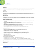
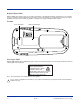
Bottom Panel Features Mechanical Connector Note: Signals referenced are for a DTE device. Mechanical Connector The bottom panel features a custom, industrial-grade connector with 17 pins. When seated in a Dolphin 7900 Series peripheral, the terminal is powered, the main battery charged, and communication occurs via this connector. All Dolphin 7900 Series peripherals are designed to work exclusively with this connector. The 17-pin connector communicates with Dolphin peripherals via RS-232 or USB.
Battery Power The Dolphin 7900 features intelligent battery technology with two types of battery power: • • The main battery pack installed in the back panel The backup battery located inside the terminal Both batteries work together to prevent data loss when the terminal is used over long periods of time. Both batteries must also be charged to full capacity before using the Dolphin 7900 for the first time. Main Battery Pack Use only the Li-ion battery packs provided by Hand Held Products.
Managing Battery Power Data and files saved on the Dolphin terminal may be stored in RAM; therefore, maintain a continuous power supply to the terminal to help prevent data loss. Letting the backup battery become fully discharged causes the terminal to lose all data in RAM. The internal battery discharges prematurely if there is not at least a partially charged battery in the terminal. When you remove a battery pack, insert another charged battery pack in the Dolphin.
Checking Battery Power Tap Start > Settings > System tab > Power. The Battery tab opens displaying the charge status of both the installed Li-ion battery pack and the NiMH backup battery inside the terminal. For more information, see Power on page 7-10. Storing Batteries To maintain optimal battery performance, follow these storage guidelines: • Avoid storing batteries outside the specified range of -4 to 104° F (-20 to 40°C) or in extremely high humidity.
Dolphin 7900 Technical Specifications System Architecture Processor: Intel X-Scale PXA255 400MHz Software Development Kits: • Dolphin SDK Add-on for Windows Mobile 2003 Second Edition (Supports Embedded Visual C++ 4.0) • Dolphin .NET SDK for Windows Mobile 2003 Second Edition (Supports Visual Studio.NET 2003 (VB.NET and C#.NET)) • Dolphin GSM/GPRS SDK Add-on for Pocket PC 2003 (Supports Embedded Visual C++ 4.0 and Visual Studio.
Dolphin 7900 Technical Specifications Operating Temperature: 14 to 122°F (-10°C to 55°C) The terminal can operate in temperatures lower than -20°C with potential degradation in performance depending on the application. Storage Temperature: -22 to 176°F (-30°C to 80°C) Humidity: 95% humidity, non-condensing ESD: 15 KVA on all surfaces Impact Resistance: Withstands multiple 5ft (1.
4 Using Dolphin Mobile Computers Overview This chapter provides the basic instructions you need to operate the Dolphin 7900 terminal. Today Screen When the terminal powers one for the first time, you see the Today screen. You can also display it by tapping Start and then Today. On the Today screen, you can see at a glance important information for the day.
Using the Touch Screen Hand Held Products recommends using screen protectors to protect the touch screen; especially when used with applications that require high-volume interfacing with the touch screen. Screen protectors help prevent damage to the touch screen display and are easily installed. Screen protectors can be purchased at any major computer retail store or directly from Hand Held Products; contact Hand Held Products directly for part numbers and pricing.
Adjusting the Backlight The backlight for the color display is user-defined. There are two tabs - one for Battery and the other for External power. The options on each tab are the same. Go to Start > Settings > System tab > Backlight. Backlight settings open displaying the Battery tab. There are two tabs: Battery and External; the options on each tab are the same. The Battery tab determines display backlight settings when the terminal is running on battery power.
Communication Options Mechanical Connector The 17-pin, industrial-grade, mechanical connector on the bottom panel is designed to work only with communication and charging peripherals sold/manufactured by Hand Held Products. For more information about the connector, see Mechanical Connector on page 3-9. IrDA Port The IrDA port enables the Dolphin 7900 to transmit data via pulses of light to and from other IrDA-compliant devices, such as printers and PCs or to other Dolphin terminals.
Radio Options Dolphin 7900 terminals can be configured with a combination of the following radios: • 802.11b - Wireless LAN (WLAN) Communications with 802.11b (see page 9-1) • Bluetooth - Wireless PAN (WPAN) Communications with Bluetooth (see page 10-1) • GSM/GPRS - Wireless WAN (WWAN) Communications with GSM/GPRS (see page 11-1) Radio Combinations Note: Configuration of simultaneous radio operation is done during the manufacturing process according to FCC regulations.
Disabling Radios To disable all radios, select None and tap Apply. Using the Soft Input Panel (SIP) Use the SIP to enter information in any program on the Dolphin terminal. You can either type on the soft keyboard or write on the touch screen using Letter Recognizer or Block Recognizer. In either case, the characters appear as typed text on the screen. To show or hide the SIP, tap the Input Panel button. Tap the arrow next to the Input Panel button to see your choices.
Tap the arrow next to the Input Panel button and then Block Recognizer and write a letter in the box. When you write a letter, it is converted to typed text that appears on the screen. Selecting Text To edit or format typed text, select it by dragging the stylus across the text. Then, use the commands on the pop-up menu to cut, copy, and paste the selected text. Input Panel Options You can set input options by going to Start > Settings > Personal tab > Input.
Writing on the Screen You can use your stylus to write directly on the screen as you would on paper. To write on the screen, tap the Pen button to switch to writing mode. This action displays lines on the screen to help you write. Note: Some programs that accept writing may not have the Pen button. See the documentation for that program to find out how to switch to writing mode. To Select Writing If you want to edit or format writing, you must select it first. 1.
For example, selected drawings can be resized, while writing cannot.
Using Find The Find feature helps you quickly locate information. Tap Start > Programs > Find. Enter the text you want to find, select a data type, and then tap Go to start the search. Using File Explorer You can also use the File Explorer to find files and organize these files into folders. Tap Start > Programs > File Explorer. You can move files in File Explorer by tapping and holding the item you want to move, and then tapping Cut or Copy and Paste on the pop-up menu.
5 Using the Image Engine Overview The Dolphin 7900 terminal houses a compact image engine that instantly reads all popular 1D and 2D bar codes and supports omni-directional aiming and decoding for greater flexibility in real-world settings. The image engine can also capture digital images, such as signatures and pictures of damaged inventory. Images are saved in industry-standard file formats. Image Engine Options Dolphin 7900 terminals may be equipped with one of the following image engines.
Bar Code Symbologies Supported The Dolphin 7900 supports the following bar code symbologies: Symbology Type Symbology Name 1D Symbologies Codabar Code 3 of 9 Code 11 Code 32 Pharmaceutical (PARAF) Code 93 Code 128 EAN with Add-On EAN with Extended Coupon Code EAN-13 Interleaved 2 or 5 Matrix 2 of 5 Plessey PosiCode RSS Straight 2 of 5 IATA Straight 2 of 5 Industrial Telepen Trioptic Code UCC/EAN-128 UPC and UPC-A 2D Symbologies Aztec Code 16K Composite Data Matrix MaxiCode OCR PDF417 QR Code RSS Compo
Activating the Engine The Dolphin 7900 terminal offers the following options to activate the engine: • The SCAN key located in the center of both keyboards for easy access from either hand; see SCAN key on page 3-2. • The buttons located on each side panel; see Side Panel Features on page 3-6. Programmable Side Buttons By default, the buttons on each side panel activate the imager; for exact location, see Side Panel Features on page 3-6.
Sample Bar Codes Use the following bar codes to verify decoding. Each bar code displays a text message on the screen when scanned. Sample 128 Bar Code Sample PDF417 Bar Code Text message: Code 128 Text message: PDF417 Test Message Omni-Directional Scanning Dolphin terminals support omni-directional scanning. The red high-vis aiming pattern frames the bar code to provide you with the best scanning performance.
Capturing Images The image-capture process is an intuitive, split-second operation for experienced users. By following the basic guidelines, new users can easily develop their own technique and, with practice, quickly learn to adapt it to different application environments. Image Preview When the imaging process is initiated, the Dolphin 7900 touch screen displays a preview of the object.
5-6 Rev D Dolphin® 7900 Series User’s Guide
6 Using the Keyboards Overview The Dolphin 7900 Series features two keyboard options: 25-key Numeric Keyboard DE L 36-key Alpha Keyboard E SC DE L BKSP SP BKSP S E ND F1 F2 E ND F3 S E ND F6 F4 S TART F9 F7 + F5 S TA R T SP E ND F1 F2 F3 F8 F4 F 10 Both keyboards are recessed under the overlay for maximum durability and backlit for maximum viewability in various lighting conditions.
Using the Function Keys Function keys are those keys that perform specific functions and usually have the name of the function they perform. Name Key Function Backlight Backspace (BKSP) Delete (DEL) The Backlight key turns the keyboard backlight on and off. BKSP DE L E SC Escape The Backspace function is performed by pressing the Red modifier key + the left arrow. Backspace moves the cursor back one space and deletes each time the key combination is pressed.
Press To … Move the cursor one character to the right. Move the cursor one character to the left. The up and down arrows can be used for • Volume up and down commands when pressed in combination with the blue modifier key, or • Page up and page down commands when pressed in combination with the red modifier key. Other functionality varies according to the application in use. Using the Modifier Keys Modifier keys are those keys that modify the next key pressed.
25-Key Numeric Keyboard The following graphic displays the 25-key numeric keyboard. Escape key Microphone DE L SCAN key OK key E SC BKSP Tab key SP ALT key S E ND Blue & Red Modifier keys F1 F2 F4 F5 F7 F8 Navigation keys F6 S TA R T Power key E ND F3 F9 F 10 Backlight key Caps Lock key Alpha Mode The 25-key keyboard defaults to numeric mode. Numeric mode is when you type numbers with the number keys. Alpha mode is when you type letters or characters with the number keys.
Blue Key Combinations Alpha Mode - Double-tap the Blue modifier key Key Character (lower case) Character (upper case) 1 _ = / \ _ = / \ 2 abc ABC 3 def DEF 4 ghi GHI 5 jkl JKL 6 mno MNO 7 pqrs PQRS 8 tuv TUV 9 wxyz WXYZ * * * . : ; - + : ; - + , @ ? ! @ ? ! Functions - Press the Blue key once in combination with the next key.
6-6 Key Combination Function/Special Character Red + 6 F6 Red + 7 F7 Red + 8 F8 Red + 9 F9 Red + 0 F10 Red + * # Rev D Dolphin® 7900 Series User’s Guide
36-Key Alpha Keyboard The following graphic displays the 36-key alpha keyboard. Escape key Microphone SCAN key OK key DE L ALT key Caps Lock BKSP SP S E ND E ND - Blue & Red Modifier Keys + S TART Tab key F1 F2 F3 NUM Lock key Power key Navigation keys Numeric indicators F4 Backlight key NUM Lock Key The 36-key keyboard defaults to alpha mode. Alpha mode is when you type letters with the letter keys. Numeric mode is when you type numbers or characters with the letter keys.
Blue Key Combinations Key Combination Function Blue + Backlight Power Blue + Left Arrow Send Blue + Right Arrow End Blue + Up Arrow Volume up Blue + Down Arrow Volume down Red Key Combinations Key Combination Function Red + Left Arrow Backspace Red + Right Arrow Space Red + ESC (hold) Soft reset (warm boot) Red + TAB (hold) Hard reset (cold boot) Red + E F1 Red + J F2 Red + O F3 Red + T F4 NUM Key Combinations Pressing the Num key once switches the keyboard to numeric mode.
Key Character WX @ YZ # Note: You do NOT need to press and hold the NUM key when pressing the next key. Numeric Shift in Numeric Mode When typing in numeric mode, tapping the Blue modifier key acts like a Shift key that enables you to type special characters in addition to those indicated on the overlay.
6 - 10 Rev D Dolphin® 7900 Series User’s Guide
7 Settings Overview Customized settings are available on the Start menu. Go to Start > Settings and settings screen opens displaying the Personal tab. Settings consists of three tabs: Personal, System, and Connections. Personal Tab System Tab Connections Tab Tab Description Personal Customizes buttons, set SIP options, and adjust headset settings; see Personal Tab on page 7-2.. System Adjusts system settings; see System Tab on page 7-7..
Personal Tab To access the Personal tab, go to Start > Settings. The screen opens displaying the Personal tab. Icon Description Buttons Program the side buttons to perform specific tasks. For more information, see Buttons on page 7-3.. Headset Adjust audio settings for headset use; see Headset Control on page 7-4.. Input Customizes the SIP. For details, see Input Panel Options on page 4-7.
Buttons Buttons programs both keyboard buttons and the side buttons to launch applications or execute commands. The default button assignments that appear on the Buttons window are inactive until you enable the HotKeys Power Tool. To Enable HotKeys 1. Tap Start > Power Tools and tap the HotKeys icon once Buttons setting are active. . HotKeys is enabled and the button assignments in the 2. Verify the assignment by tapping the button on the keyboard.
Command Description Nothing happens when the button is pressed. This is the default setting for the LSide and RSide buttons and means that pressing either button activates the image engine. Performs the same function as tapping OK on the screen. Scrolls down in the open application. Scrolls left in the open application. Scrolls right in the open application. Scrolls up in the open application.
Menus - Adding a Program to the Start Menu You can add existing programs you use often, such as File Explorer, to the Start menu for faster access. You are not installing the program, just allowing access to it from the Start menu. Note: The Start menu can hold only seven applications total. Using System Settings 1. Tap Start > Settings > Personal tab > Menus > Start Menu tab. 2. Tap the check box for the program you want to add and tap OK to save. 3.
3. Navigate to the Windows folder and open the Start Menu (My Device > Windows > Start Menu), tap and hold a blank area of the window, and tap Paste Shortcut on the pop-up menu. 4. Tap the Start menu to verify that the program now appears on it. Using ActiveSync on the Desktop Computer Here, you are performing the same basic process as on the terminal, except that you are using the Explore utility (Windows Explorer) to copy and paste the shortcut. 1. Open ActiveSync > Explore and navigate to the program.
System Tab The System tab enables you to verify and sometimes alter system parameters. To access the System tab, go to Start > Settings > System tab. Tap the appropriate icon to open that system setting. About The About system setting displays specific information about what is loaded on the terminal. It contains three tabs: Version tab Displays the information about the software, operating system, and processor of the terminal.
CPU Speed This system setting enables you to see and change the current speed of the Central Processing Unit (CPU). The default is High Speed at 400MHz. Low Speed is 200MHz. To change the default, select Low Speed and tap OK. A message appears confirming the new CPU speed. Tap OK to save the change. Memory The Memory system setting enables you to review and manage both RAM (volatile) and IPSM/Storage Card (non-volatile) memory. Access this system setting whenever you receive system messages about memory.
Storage Card Tab IPSM This tab displays the current capacity and usage statistics of the selected memory type; IPSM or Storage Card. Select the memory type from the drop-down list. IPSM is selected by default. Total storage card memory The total MB of memory capacity of the selected memory. In use The MB currently being used. Free The MB that is still available for use. Short for Intel Persistent Storage Manager, this is14MB of on-board Flash memory that is nonvolatile.
• Tap Stop All to automatically stop all running programs. Anytime you stop a running program, it frees up RAM memory. Be advised that, when you stop a program here, any unsaved data in that program is lost. To free up memory without risking data loss, return to the running program, save your data, and close the application. ! Find Link Underneath the three Memory tabs is a link to the Find window that enables you to search for large files using storage memory.
Tab Description Advanced Tab Determines power time-outs. For On battery power, select from the drop-down list, the number of minutes of inactivity you want to pass before the terminal powers off when running on battery power. For On external power, select from the drop-down list, the number of minutes of inactivity you want to pass before the terminal powers off when running on external power.
Remove Programs The Remove Programs settings enables you to remove programs installed on the terminal. Use this setting to troubleshoot when you receive messages that the device is out of memory. The programs removed are removed from RAM memory. Any program (usually *.cab or *.dll files) stored in the Autoinstall folder (My Device > IPSM > Autoinstall) will re-install after the next hard reset. For information about the Autoinstall process, see Let Autoinstall Run on page -7.
Alignment tab The Screen system setting opens to the Alignment tab. On this tab, you can re-align the screen. Remember, you first align the screen at bootup. You would need to re-align the screen again if tapping buttons or icons with the stylus no longer seems to work appropriately. For more information, see Align the Screen on page 2-7.. ClearType Tab The Dolphin 7900 displays support ClearType font rendering.
This is the default font size setting. To change the font size, move the slider toward Smallest or Largest. The Example text changes to reflect the font change. Tap OK to save the new font size setting.
Connections Tab The Connections tab enables you to manage your network connections. Icon Tapping this icon… Beam Enables you to verify and adjust the infrared settings of the IrDA port; see Using Infrared on page 8-5.. Connections Enables you to configure network connections. This is the connections manager; see Connections Tab on page 7-15.. Network Cards Enables you to access the Wireless and Network Adapters tabs; see Network Cards on page 7-24..
Com Port Assignment 3 Raw Infrared 4 Unassigned 5 USB virtual serial port 6 IrDA, if IrDA is enabled. If IrDA is disabled, this com port becomes available. See Verify That the IrDA Port is Enabled on page 8-5. 7, 8, 9 Unassigned; these are virtual com ports that are available for selection only when connecting to devices that use virtual com ports, such as Bluetooth. Opening the Connections Manager To open the connections manager, tap Connections.
• TCP/IP settings. 2. Use a NULL modem cable to connect to an external modem. 3. Tap Start > Settings > Connections tab > Connections > Task tab. 4. Tap Add a new modem connection. The Make New Connection screen appears. 5. Enter a name for the connection, such as "My Connection." 6. In the Select a modem list, select the external modem by selecting Hayes Compatible on COM1. 7. Tap Next. The My Connection screen appears. 8. Enter the number that should be dialed when connecting to your ISP.
General Tab Use the General tab to change the connection speed. Wait for dial tone, dial, then wait for credit card, add dial-string modem commands, or cancel call after a set number of seconds. Port Settings Tab The Port Settings tab has options that should be left alone unless indicated otherwise by your ISP. TCP/IP Tab If your ISP does not use a dynamically-assigned address, enter that information into the TCP/IP tab.
Servers Tab Finally, if your ISP requires special DNS or WINS information, enter it into the Servers tab. Connecting to Your ISP 1. Tap Start > Settings > Connections tab > Connections to open the connections manager. 2. Tap Manage existing connections. 3. Tap and hold on the applicable dial-up settings and select Connect. (You can delete the connection by selecting Delete.) 4. Your modem will dial-out and attempt to create the connection.
3. Tap Exceptions. The Work URL Exceptions screen opens. 4. Enter the Work URL and tap OK. Setting up a Proxy Server Connection for Work Connections If you are connected to your ISP or private network during synchronization, the terminal should download proper proxy settings during synchronization from your PC.
2. Under the My Work Network heading, tap Add a new VPN server connection. 3. Enter the requested information including VPN type and tap Next. 4. Indicate whether a pre-installed certificate should be used or rather a pre-shared key and tap Next. 5. Enter your login details. If finished, tap Finish to complete VPN setup. 6. Otherwise, tap Advanced to access more options. • Enter TCP/IP settings in the TCP/IP tab; server-assigned IP addresses use DHCP.
• Enter Server DNS/WINS information in the Servers tab. Connecting to a VPN Server 1. Go to Start > Settings > Connections tab > Connections. 2. Select Edit my VPN servers. 3. Tap and hold on the server, then select Connect on the popup menu. (Note that through this screen you can delete your VPN server connection.) 4. Your VPN Server is accessed.
Establishing Dialing Rules 1. Tap Start > System > Connections tab > Connections > Advanced tab (see page 7-16). 2. Tap Select Location. 3. Select Use dialing rules. By default two dialing rules profiles exist: Home and Work. 4. Tap Edit to configure either profile. (You can define your own dialing profile by tapping New. A warning appears that your existing modem connections must include the correct country and region area code settings. 5. Tap OK to confirm.
6. Tap Dialing Patterns to change how dialing occurs. 7. Following the format of "e" represents country code, "f" represents area code, and "g" represents the number, enter how local, long distance, and international calls should be dialed. Tap OK to save your changes. Creating a Wireless Network Connection In the Connections Manager, you can access the Wireless tab from Start > Settings > Connections tab > Network Cards > Wireless tab.
3. If you make a change on one of these tabs, tap OK. The following message appears: 4. You must perform a soft reset to update the registry; see Soft Reset (Warm Boot) on page 2-9.. During the soft reset, the new registry entries created by the changes can be read by the applications that need them. ! Do NOT perform a hard reset (see Hard Reset (Cold Boot) on page 2-9) after modifying an adapter here.
7 - 26 Rev D Dolphin® 7900 Series User’s Guide
8 Communications Overview You can exchange information between your Dolphin terminal and other mobile devices, a desktop computer, a network, or the Internet using the following connection options: • Connect to a desktop computer and synchronize via Microsoft ActiveSync v3.7 or higher; see page 8-4. • Use the infrared (IrDA) port to send and receive files between two devices; - see page 8-4. • Connect to an ISP via wireless radio; see page 8-8.
Using ActiveSync Using Microsoft ActiveSync, you can synchronize and transfer information between your desktop computer and Dolphin terminal. The most current version of ActiveSync can be downloaded from www.microsoft.com. Additional Capabilities With ActiveSync, you can also: • Back up and restore your device data. • Copy (rather than synchronize) files between your device and desktop computer. • Control when synchronization occurs by selecting a synchronization mode.
To initiate synchronization the first time, tap Start > Programs > ActiveSync. The synchronization process begins. Note: If you have a wireless LAN card, you can synchronize remotely. After the first synchronization, when using Dolphin peripherals such as the HomeBase or Mobile Base, synchronization begins automatically whenever a terminal is properly seated in the terminal well. For more information, see Dolphin HomeBase on page 13-1 or Dolphin Mobile Base on page 14-1.
The terminal is now treated as a mass storage device, and transferring files is as simple as dragging and dropping or copying and pasting as you would for moving files between folders on your hard drive. Adding Programs to the Terminal Using ActiveSync ! When selecting programs, verify that the program and version of the program are designed for Windows Mobile 2003 Second Edition and your processor. You can verify your processor by tapping Start > Settings > System tab > About > Version tab.
Using Infrared Dolphin 7900 terminals contain an IrDA port on the top panel (see IrDa Port on page 3-2). Using the IrDA port, you can send and receive data between the terminal and other devices equipped with infrared. This can include, but is not limited to, Windows Mobile information such as Contacts and Tasks, as well as software upgrades. Verify That the IrDA Port is Enabled The IrDA port must be enabled to transmit data. By default, the IrDA port is assigned to Com port 6 and is enabled.
Verify That Beam Settings Are Set to Receive The Beam Settings must be set to receive for the terminal to receive data from other infrared devices. To verify, tap Start > Settings > Connections tab > Beam. The Beam Settings window should appear as follows: Sending and Receiving To send or receive, the IrDA ports of both devices - whether it’s two terminals, or a terminal and a host device - must be aligned with each other and within a close range. The maximum data-transfer speed is 115 Kbps. Sending 1.
Troubleshooting If the Beam Settings are not set to receive or you’ve aligned two IrDA ports and the terminal is still not receiving, go to Start > Programs > Infrared Receive. The terminal searches for the sending device.
Using an ISP The communication software for creating an ISP connection is already installed on your device. Your service provider should provide the software needed to install other services, such as paging and fax services. After you are connected, you can send and receive e-mail messages by using Inbox and view web pages using Pocket Internet Explorer. For more information, see Messaging on page 12-7. You can also download software applications from the web.
9 Wireless LAN (WLAN) Communications with 802.11b Overview Dolphin terminals are available with an on-board 2.4 GHz 802.11b WLAN (Wireless Local Area Network) radio that uses Direct Sequence Spread Spectrum (DSSS) technology to spread the signal continuously over a wide frequency band at a data rate of up to 11 Mbps. In addition, the open software architecture makes the Dolphin terminal a complete solution for a variety of wireless mobile data collection applications.
802.11b Settings You can access the configuration utility two ways: 1. Tap Start > Settings > System tab > 802.11b Settings. The icon appears on the System tab only if there is an 802.11b radio installed on the terminal. 2. Tap the Status icon in the system tray - see Using the Status Icon on page 9-9. The 802.11b Settings utility consists of four tabs: Status, Config, Advanced, and About. Each tab is described in its own section in this chapter.
Status Tab 802.11b Settings always opens to the Status tab. Field Description Current Channel Shows the RF channel currently used by the radio. Current TX Rate Shows the current transmit rate. This can be 1 Mbps, 2 Mbps, 5.5 Mbps, or 11 Mbps. Disable/Enable Radio Tap this button to disable/enable the radio. Rescan Tap this button to start a rescan process to search for an AP with a stronger signal in the network. Link Quality Displays the signal to noise ratio.
Ping Utility Window Field Description IP Address Displays the current IP address. Enter another IP address to ping. Size (Bytes) Displays the current data packet size in bytes; 32 is the default. You can select up to 8192 from the drop-down list. Timeout (ms) Displays the current timeout; 500 is the default. Increase or decrease it by tapping the up and down arrow buttons. Clear Tap this button to clear IP Address input and the ping statistics field.
This section contains several icons that enable you to add and configure APs. Icon Name Description New Always active, tap this button to create a new profile. The following buttons activate only when an Active SSID in the Preferred Profile list is selected. Edit Opens the configuration screens for a selected SSID in the Preferred Profiles list. Delete Deletes the selected SSID from the Preferred Profile list.
2. In the Preferred Profile list, select the SSID and tap Edit . 3. Follow the same process for creating a profile. 4. When configuration is complete, tap OK. 5. The SSID and its profile are added into the Preferred Profiles list. If you’re adding an SSID with the WEP Key turned off, the Settings window does not display and the SSID is added directly to the Preferred Profile table. To Create a New Profile In the Preferred Profiles section, tap the New button .
Authentication Tab On the Authentication tab, you configure the WEP encryption key for secure wireless communication. To use WEP, the encryption key must be configured as part of the profile before connecting. For more information about configuring a profile, see To Create a New Profile on page 9-6. Field Description *Authentication Algorithm This drop-down list is active and configurable only when the WEP Key is enabled for the selected SSID profile.
To Delete a Profile Profiles may be deleted either from the Preferred List or from the Preferred List and Registry. To delete a profile, select (highlight) a profile and tap the Delete button and the following screen displays: From the pop-up window select the option of your choice and tap Yes to confirm or No to cancel. Advanced Tab Field Description Power Save Mode This drop-down list determines the settings for Power Save Mode. Disable – Disables the Power Save mode.
Field Description Defaults Resets all the settings to default values • • • Apply Always Enable for Power Save Mode, Automatic based on WEP setting for Authentication Algorithm, and Auto TX Preamble (for Preamble Mode). Applies changes. This button is active only when a change has been made on the tab. About Tab The About tab displays Version Number and time of build for Network Driver, Configuration Utility, and NIC Firmware. Using the Status Icon You access the 801.
802.11b Wireless Security Supplement AEGIS Client® offers the most comprehensive IEEE 802.1X supplicant for securing wired and wireless networks. The Client is a standards-based implementation of IEEE 802.1X and can be configured to work with almost any network equipment - wired or wireless - that supports the 802.1X authentication standard. The Client is interoperable with 802.1X-capable wireless APs and authentication servers including Microsoft's IAS and Cisco's ACS.
• TLS/SmartCard • TTLS • PEAP There is a worksheet for each method. The worksheets provide space to record the required Client configuration information to set up the Client to match specific Extensible Authentication Protocols (EAP). The forms are designed so that hard copies can be filled out, copied, and distributed. Complete a worksheet for the authentication method you choose. MD5 Worksheet To configure AEGIS Client to use MD5 authentication, you need to know: 1.
____ No. ____ Yes. 5. What is the name of the server? _____________________________ This usually includes the server’s domain, for example: server.big_school.edu. TTLS Worksheet To configure with TTLS authentication, you need to know: 1. Use Windows user name and password for authentication? (Applies only to Windows clients.) 2. If not, what is your unique user name? If a second set of credentials is required, you need to know the exact user name. This is usually case-sensitive.
10. What is the name of the server? This usually includes the server’s domain, for example: server.big_school.edu. _____________________________ PEAP Worksheet To configure AEGIS Client with PEAP Authentication, you need to know: 1. Use Windows user name and password for authentication? (Applies only to Windows clients.) 2. If not, what is your unique user name? If a second set of credentials is required, you need to know the exact user name. This is usually case-sensitive.
Opening the Client To access the client the first time, tap Start > Programs > Meetinghouse AEGIS Client. After the Client has been activated, you can tap the icon in the lower left corner of the command bar. Icon Indicators The color of the icon indicates the status of the controlled ports. Icon Color This color icon indicates that … Green Authentication succeeded. Yellow Authentication is in process. Red Authentication failed.
Main Screen On the terminal, open the Client. The main screen opens displaying a list of ports on the system’s network interface cards, You manage ports on this screen. Port Status icon Port Status Icon The main screen contains a port status icon to the left of each port listed. The color of this icon indicates the status of the port. The color of the icon changes as the port starts authentication, negotiates with the AP and/or authentication server, and then joins the network.
Menu Item Tapping this item… Start/Stop Starts or stops 802.1X authentication. After you finish the initial configuration, tap the network interface and tap Start. If the port is already active, tap Stop first, then Start to force the program to read the new configuration file. Restart Same as a Stop followed by Start. Tap this when you receive a notice such as the following: Configure Opens the Configuration screen displaying the User tab. Install Protocol Selecting this option binds the 802.
Menu Item Tapping this item… Each entry is listed sequentially with a time stamp and a text message. Tap Refresh to query the log again. Tap Close to return to the main screen. Help Menu Tapping Help opens the help menu. Select Online Help to access online help. Select About to review software version information. Status Bar The status bar at the bottom of the main screen indicates the connection status between the network card and the AP.
Port Menu On the main screen, tapping on a port opens a popup menu that allows the port to be enabled or disabled, configured, or deleted. Port Menu Options The port menu enables you to use 802.1X authentication, change the port configuration, or remove it from the port list. If there are no entries in the Port list, follow the advice in the troubleshooting section to resolve the problem. Menu Item Description Enable and Disable These commands enable or disable 802.1X authentication on the port.
Configuration Screens Both Client Configuration and Port Settings areas lead you through a series of setup screens. The following diagram displays the different screens and how they are related: Client Configuration Area Each user account needs to define the protocol and the credentials used to authenticate a user. Because Windows Mobile devices are usually small devices with a single NIC and, usually, a single user, the initial configuration is usually the only time the software needs to be set up.
User Tab The User settings tab defines the protocol and the credentials used to authenticate a user. Field Description Profile Multiple user credential profiles can be created for use when the user roams from one network to another. The drop-down list contains existing authentication credential profiles. Select a profile from the list to edit it in the fields that follow. Tapping Add permits new profiles to be added to the list. A screen appears where you can enter a name for the new profile.
Field Description Use certificate This is the certificate to be used during authentication. A certificate is required for TLS, optional for TTLS and PEAP, and unused by MD5 and LEAP. Therefore, this option becomes active only when TLS, TTLS, or PEAP is selected as the Authentication type. If Use certificate is enabled, the client certificate displayed in the field is the one that is passed to the server for verification.
System Tab The System Settings tab controls logging and the port manger timeout period. Field Description Log Level These settings control the detail of the log messages generated by the Client. Each level is cumulative. By default, all errors, warnings, and information events are logged. Each entry records a severity code (of one [debug message] to four [error] asterisks), a time stamp, and a message. • Errors - only the most severe conditions are logged. • Warnings - less severe conditions are logged.
Server Tab The Server identity tab defines the credentials the client uses to authenticate the server during TLS/TTLS/PEAP authentication message exchange. The Client uses this information to verify that the Client is communicating with a trusted server. Field Description Do not validate server certificate chain If this option is selected, the server certificate received during the TLS/TTLS/PEAP message exchange is not validated.
Wireless Networks Tab Field Description Available Networks Displays the networks the terminal recognizes as available to connect to. When the Client is first installed, there are no entries in the Available Networks list. Scan Displays a list of networks broadcasting their availability. You can also attach to networks who are not broadcasting. Move to Configured Activates after Scan has been tapped and the available networks have been retrieved.
Protocol Tab The Protocol tab configures parameters that apply to all the networks the selected port connects to. Field Description Protocol Settings These are the timer intervals and retry settings defined in the 802.1X standard. They determine how long the supplicant state machine will wait in a given state. These parameters shouldn’t be modified without an understanding of the supplicant state machine. For more information about the supplicant state machine, obtain its 802.1X protocol specification.
Adding a Wireless Network Configuration To add a wireless network configuration, on the main screen, tap and hold on the port, tap Configure on the Port popup menu, then tap Add in the Network Configurations section of the Wireless Networks tab. The Network Profile screen opens displaying the Profile Info tab. Note: The settings on these tab windows are interrelated. This means that selecting one may disable access to others.
WEP Mgmt Tab The WEP Mgmt tab enables you to set WEP parameters for each port. Field Description Provide encryption key dynamically This option is selected by default. If this option is selected, the other WEP settings on this page are disabled. To enter a custom WEP, de-select this option. The other fields become active. Use key for data encryption Select this option to manually enter a WEP key to encrypt your data to the AP. You enter that key in the Key field below.
WPA Settings Tab The WPA Settings tab enables you to configure WPA settings. Field Description WPA Mode This drop-down list contains the following options: • Disabled - Do not enable WPA mode. This is the default selection. • WPA 802.1x - Enable WPA and obtain key information through the 802.1x protocol. • WPA PSK - Enable WPA with Pre-Shared Key (PSK) information entered in the field below. This mode is used if the 802.1x protocol is not being used for authentication.
Installing Certificates with CertAdd Certificate Requirements During configuration, you may have specified one or two certificates to use during the authentication process. The specified identity should match the Issued to field in the certificate and should be registered on the authentication server (i.e., RADIUS server) that is used by the authenticator. In addition, your certificate must be valid on the authentication server.
Advice and Workarounds Issue Possible Causes and Solutions The wireless network interface appears, but when I select it and go to the "configure" menu, the Scan button is disabled. Power up the radio; see Enabling Radios and Radio Combinations on page 4-5. The client is not attaching to the correct AP. The default network profile instructs the client to attach to the first available AP.
How 802.1X Works The network elements in the above graphics are those involved in a typical wireless LAN. When 802.1X is running, a wireless device must authenticate itself with the AP in order to get access to the Existing LAN. With respect to the terms used in the 802.1X standard, APs (APs) function as authenticators and wireless devices function as supplicants. The authenticator keeps a control port status for each Client it is serving.
Typical Message Exchange Using TTLS and PEAP The above graphic shows a typical message flow for a TTLS transaction. TTLS authentication comprises two phases. In Phase 1, TLS is used to authenticate the TTLS server to the client. The TTLS server may optionally request authentication of the client's certificate, but by default the client verifies only the server's certificate. The TLS handshake is negotiated between the client and the TTLS server.
Dynamic Session Specific Wireless Encryption Keys There have been many published reports recently about the lack of security provided by the Wired Equivalent Privacy (WEP) protocol. One of the problems with WEP is that the shared key used by the station and the AP is inherently static. That is, this shared key will only change if it is manually reconfigured on both devices. The Client remedies this by supporting the Transport Layer Security (TLS) protocol.
Differences Between Protocols Security Feature MD5 Challenge TLS TTLS PEAP LEAP Client -side certificate required? No Yes No No No Server-side certificate required? No Yes No Yes No Dynamic WEP Re-keying No Yes Yes Yes Yes Mutual or One-way Authentication? One-way Mutual Mutual Mutual Mutual Support of non-EAP protocols within a secure tunnel? N/A N/A Yes No N/A Relative Deployment Complexity Simple Difficult Moderate Moderate Moderate Relative Security Poorest Hi
10 Wireless PAN (WPAN) Communications with Bluetooth Overview Dolphin terminals are available with a Bluetooth radio for WPAN (Wireless Personal Area Network) usage. When the Dolphin is first initialized, the *.cab file and module for Bluetooth are installed. Enabling the Bluetooth Radio Before using the radio, make sure that the Bluetooth radio is enabled. When the radio is enabled, the Bluetooth icon appears in the task tray on the Today screen.
1. Tap on the Bluetooth icon on the Today screen. Select Advanced Features then My Bluetooth Device. Note: If you installed OBEX, the menu also lists Transfer via Bluetooth. 2. The My Bluetooth Device screen appears. Tap on the COM Ports tab. 3. As needed, view and/or enable/disable the Bluetooth COM port assignments. Tap OK. You can also disable the IrDA port to free up a port for Bluetooth devices. Tap Start > Settings > Connections tab > IrDA and select Disable IrDA Port.
3. Follow the Bluetooth Device Discovery Wizard to search for Bluetooth devices nearby. When prompted, select the device type you seek. 4. When the search is complete, a screen reports the discovered Bluetooth devices. Check the box next to any device you wish to save information about, (i.e., any devices you wish to connect to). Tap Next. 5. A service discovery phase begins, 5-10 seconds per chosen device. 6. In the next screen, tap Finish.
2. Tap and hold your stylus on the Bluetooth device you want to bond with. In the pop-up menu, select Bond. 3. Alternatively, after selecting a device, tap on the Bond icon. Or tap on Device, then select Bond. 4. The Bluetooth Device Bonding Wizard launches. Follow the wizard to bond with your selected device. 5. As prompted, make sure the Bluetooth device that you want to bond with is in Bondable mode.
6. If the remote device is set up to accept bonding, a Bluetooth Passkey screen appears. To continue bonding, enter the correct passkey and tap Reply. 7. When you have successfully bonded with the other device, tap Finish. View Device Properties Follow these steps to view the properties of an already discovered device. 1. If not open, launch the Bluetooth Devices folder. Tap on the Bluetooth icon on the Today screen. Select Advanced Features then Bluetooth Devices. 2. Select a device.
2. Tap on the tab for the type of device you would like to set a favorite for. If needed, use the arrow buttons to scroll and find the tab you need. Note: Tabs appears only for COM ports you have enabled. To enable a port, refer to the “Assign COM Ports” section earlier in this chapter. 3. To select a favorite device, select Use the favorite selected above. In the drop-down list, select your device. Tap OK. 4.
2. Tap and hold your stylus on the device you wish to delete. In the pop-up menu, select Delete. Turn Radio Transmitter ON/OFF You may want to turn off the radio transmitter to save power or if you are entering an area with radio restrictions (e.g., an airplane). 1. Tap on the Bluetooth icon in the task tray on the Today screen. 2. In the pop-up menu, select Turn Transmitter OFF. 3. The Bluetooth Card radio transmitter shuts off. The Bluetooth icon and menu options becomes gray. 4.
(a) When you tap on Bluetooth ActiveSync, a screen appears that allows you to choose which computer to connect to in your Bluetooth Devices folder. Choose a computer from the list and tap Select, or tap Find to search for another computer. Note: If the computer you want to connect to is not listed, tap Find to begin a search. Proceed as described in Scenario #3 on page 10-8. (b) Your device attempts to connect to your selected computer.
(d) The Connect To screen appears, reporting that it is trying to connect to Wireless ActiveSync. (e) After a successful connection is made, the status screen reports Connected. Now you are ready to synchronize, if desired. Bluetooth LAN Access This section explains how to use the Bluetooth LAN Access feature to quickly and easily connect to a Bluetooth-enabled LAN access point. 1. Tap on the Bluetooth icon. In the pop-up menu, select Bluetooth LAN Access. 2.
(a) When you tap Bluetooth LAN Access, the device automatically tries to connect with your favorite access point. (b) If your LAN requires a passkey, a screen appears, asking for the passkey. Enter the passkey, then tap OK. (c) After a successful connection is made, the status screen reports Connected. (d) Now you are ready to access your LAN for Internet access, files, etc. SCENARIO #3: Your Bluetooth Devices folder has no access points.
OBEX This section explains how to use the OBEX (object exchange) application to trade business cards, contacts or files with another Bluetooth device that supports OBEX. Bluetooth OBEX application supports five operations: • • • • • • Exchange Business Cards Send a Contact Send a File Browse Remote Device Receive Contact or File Enable File Sharing The first four operations - exchange business cards, send a contact, send a file, and browse remote device - are client-oriented.
3. Now you are ready to exchange business cards. Tap on the Bluetooth icon. In the pop-up menu, tap Transfer via Bluetooth > Exchange Business Cards. 4. If your device has no devices in the Bluetooth Devices Folder, then it begins to search for Bluetooth devices nearby. 5. Select the Bluetooth device you wish to exchange business cards with. If the device is not listed, tap Find. 6. Your device begins exchanging business cards.
4. If your device has no devices in the Bluetooth Devices Folder, then it begins to search for Bluetooth devices nearby. 5. Select the Bluetooth device you wish to send the contact(s) to. If the desired device is not listed, tap Find. 6. Your device processes and sends the contact(s). Send a File 1. Make sure the other Bluetooth device can receive a file; that device must support the OBEX Object Push server profile.
4. Select the Bluetooth device you wish to send a file. If the desired device is not listed, tap Find. 5. In the next screen, tap on the file you wish to send. You can use the Folder and Type drop-down menus to search for your file. Also, you can scroll horizontally to view the folder, date, size, type, and location of each file. 6. Your device sends the file. Browse Remote Device The Bluetooth File Explorer lets your device share files with another Bluetooth device.
2. Now you are ready to browse the remote device. Tap on the Bluetooth icon. In the pop-up menu, tap Transfer via Bluetooth > Browse Remote Device. 3. If your device has no devices in the Bluetooth Devices Folder that supports OBEX File Transfer, then it begins to search for Bluetooth devices nearby. 4. Select the Bluetooth device you wish to browse. If the desired device is not listed, tap Find. 5. Your device begins to establish a file sharing connection. 6.
Send/Receive File(s) or Folder(s) • Single-tap items to select them for transfer. • Double-tap on a folders to open it and see its contents. 1. Select the file(s) or folder(s) that you wish to transfer. You can select items from only one device per transfer session. 2. There are two different ways to initiate the transfer: • Tap File > Send to remote or Get from remote, as applicable. The inappropriate option should be gray. • Tap on the Send to remote icon or Get from remote icon, as applicable.
Delete File(s) or Folder(s) 1. Select the items you wish to delete. You can only delete items from one device at a time. 2. Tap on the File menu. Select Remote device or Local device, wherever the items are located, then tap Delete remote item(s) or Delete local item(s), as applicable. 3. Tap and hold your stylus an item in either the remote or local device that you wish to put in a new folder. In the pop-up menu, select Delete folder. 4. In the Confirm screen, tap Yes. Refresh Remote View 1.
Exit Bluetooth File Explorer To exit the Bluetooth File Explorer, tap File > Exit. Receive Contact or File 1. Tap on the Bluetooth icon. In the pop-up menu, tap Transfer via Bluetooth > Receive Contact or File. 2. The Receive Contact or File status screen appears. Your device waits two minutes for the contact or file. 3. After successfully connecting to the remote device, the screen reports Connected then disappear. The new contact or file should now be on your device. 4.
Assign a Dialing Prefix If you have not already assigned a dialing prefix during the install process, you can do so by following these steps: 1. Tap Start > Settings > System tab > Dialer. 2. Select the appropriate Dialing Prefix, then tap OK. Using the Dialer 1. To use the dialer, the device must already be connected to the Bluetooth phone. You can use the Get Connected! Wizard to do this. Also, the Bluetooth phone must be selected as your favorite. 2. Tap Start > Contacts. 3.
5. Your device connects to your phone and begins dialing. The Dialer can dial a phone number containing any of the following non-numeric characters: * # + . / ! @ - \ space A B C D T P W The following string can also be included in a phone number: (',') The Dialer cannot dial a phone number containing non-numeric characters other than those listed above. HHP recommends that you follow the standard Microsoft Outlook format for phone numbers.
(c) Preparing your Bluetooth passkey. 4. When the search is complete, a list of the discovered Bluetooth phones appears. Choose the phone you wish to connect to, and tap Select. A service discovery phase begins, about 5-10 seconds. 5. As prompted in the next screen, prepare your phone for bonding. For instructions on setting your phone to “Bondable” or “Pairable” mode, refer to your phone manual. Have your passkey ready, then tap Next>. 6. In the next screen, enter the passkey. Tap Reply. 7.
3. As directed on the next two screens, assign the phone a unique name, set the phone to Discoverable mode, and tap Next. 4. The device searches for the phone. When the search is over, a list of the discovered Bluetooth phones appears. 5. Choose the phone you want to connect to, and tap Select. A service discovery phase begins, about 5-10 seconds. 6. The next two screens describe procedures you complete outside of the wizard.
1. Tap Start > Settings > Connections tab > Connections. 2. In the top field, select Internet Settings and tap Modify. Then, tap New. 3. Name=A name that you will remember for future connections. Modem=Bluetooth Phone. Baud Rate=115200. 4. Tap Next. 5. In the Phone number field, enter the dial-up number. Tap Next. 6. Uncheck Wait for dial tone before dialing. Tap Finish. 7. Now you are ready to start the connection. In the Connections screen, under Internet Settings, tap Connect.
• Scroll to the right tab to access the Paired devices list. Highlight your mobile computer, then press OPTIONS. • Scroll to Set as authorized, then press SELECT. • In the confirmation screen, press YES. Automatic Connections for Nokia 6310/8910/8910i: • • • • • On the phone, press MENU. Scroll to 10 Bluetooth, then press SELECT. Scroll to 4 View Paired Devices, then press SELECT. Highlight the Dolphin terminal, then press OPTIONS. Scroll to 3 Request Connection Authorization, then press NO.
11 Wireless WAN (WWAN) Communications with GSM/GPRS Overview Dolphin terminals can be configured with a Siemens® GSM/GPRS tri-band radio module for Wireless WAN connectivity. GSM GSM stands for Global System for Mobile communications. It is an open, non-proprietary wireless wide area networking system that is constantly evolving and growing. One of its great strengths is international roaming capability, which provides standardized dialing in more than 170 countries.
SIM Card SIM stands for Subscriber Information Module. A SIM card stores the subscriber's personal information, GSM/GPRS radio settings, security key, contacts, etc. SIM cards can be installed and removed from compatible mobile devices, enabling you to switch devices without losing your personal information. SIM cards are obtained and activated by the network provider that supports your GSM/GPRS network.
Using uPhone The uPhone Application Suite contains three programs that function together to provide a complete voice, data, and text messaging solution for a mobile device fitted with a radio modem: • Dialler emulates a mobile phone and is used to make and receive telephone calls. • Call Log displays a list of the most recent calls. • SMS Manager is a text messaging program. Accessing uPhone Tap Start > Programs > uPhone. Tap one of the icons to launch the program.
Icons and Bubble Messages Icon Description Tap this icon to display: Bubble Options Good signal strength. Full signal strength. Incoming SMS message available. Tap View to display the full message in SMS Manager. This bubble appears automatically when a new SMS message is received. It contains the sender’s information and the first line of the text message. Tap Reply to switch to the SMS Manager Compose screen. The 'To:' field is autofilled with the sender’s address.
Using the Dialler The Dialler is the is the program that manages your GSM/GPRS cell phone calls. To launch the Dialler, tap Start > Programs > uPhone > Dialler. The program launches and the uPhone Dialler screen opens: Three information lines: Dialler screen Network–name of service provider. Number/Name–dialed, incoming, and outgoing calls. Status–status of the phone. Signal Strength Four bars is optimal.
• Tap the Send button . • Press the ENTER key on the keyboard. • Press the appropriate key combination on the keyboard. When the call is connected, the three information lines display the following: Network Operator Displays the name of the service provider you are using. Name/Number Displays the name and/or number you called. If the number is from your Phonebook, that entry displays. Status The status of the call. Idle - means no calls are incoming or outgoing.
Ending a Call To end or reject a call, you can: • Tap the End button . • Press the appropriate key combination on the keyboard. Call Waiting If two calls are in progress, the above options end the active call and place the other on hold. To activate the call on hold, tap Send or press ENTER or the key combination to send calls. To end the call on hold, tap End or press the key combination to end calls on the keyboard.
Button Tapping this button… Hide Closes the bubble. Touchtones To transmit touchtones for interactive voice systems while in a call, you can • Tap the 0-9, *, and # buttons on the uPhone Dialler screen. • Press 0-9 keys on the Dolphin keyboard; use the uPhone Dialler screen buttons for * and #. Dialler Menus There are three menus in the Dialler application: 1. Tools - Accesses application tools. 2. Settings - Opens application settings. 3. Help - Opens the About screen.
Menu Item Description See Page USSD Sends text messages via USSD as opposed to SMS. 11-12 Exit Exit the uPhone Dialler. Settings Menu Speakerphone Toggles speakerphone mode on and off. When an audio plug (for a headset) is inserted into the audio jack (2.5mm), Speakerphone is inactive on this menu. Mic mute Toggles microphone mute on and off (the other party cannot hear a private conversation when the microphone is muted).
Ringtone Configuration Different ringtones, with individual volume settings, can be set for the following: Ring Tone Sounds on an incoming call. Message Tone Sounds on an incoming SMS or Voicemail notification. Call Waiting Tone Sounds to indicate an incoming call while you are already on a voice call. You can access Ringtones two ways: 1. Tap Start > Settings > Personal tab > Ringtones icon OR 2. Open the Dialler (tap Start > Programs > uPhone > Dialler) and tap Tools > Ringtones.
Charging Accessed from the Tools menu, the Charging tool displays call meter values from the network service provider. Tap Tools > Charging and the Charging window opens displaying the current values for the phone. Field Description Call meters Current call Displays the number of charge units used on the current call. Accumulated calls Displays the number of charge units used to date. Maximum available Displays the maximum number of units available from the subscriber.
USSD Short for Unstructured Supplementary Service Data, (USSD) is a technology unique to GSM that enables session-based textmessaging as opposed to SMS, which is store-and-send text-messaging. Turnaround response times for interactive applications are generally shorter for USSD than SMS. USSD is not currently available on all carrier networks. USSD communicates with a USSD application portal, a news portal or a chat session with a co-worker. Tap Tools > USSD.
Call Log The Call Log maintains a list of the last 20 calls made or received in each of the following categories: • • • • Voice Calls In (Default) Voice Calls Out Voice Calls Missed GPRS Data You can access the Call Log two ways: 1. Tap Start > Programs > uPhone > Call Log OR 2. Open the Dialler and tap Tools > Call Log. The Call Log opens displaying the last few Voice Calls In; the most recent call always appears at the top.
uPhone Configuration uPhone Settings enable you to establish the normal operating parameters for uPhone applications. Requirements To open the uPhone configuration tools, the GSM radio must be enabled and an active SIM must be installed. The configuration tools access the network directly. If you are not connected, settings cannot be configured and you will receive an error notification when you attempt to open the configuration tools.
General Tab Field Description Phone Number This is the phone number stored on the SIM. It is displayed here for information only. Answerphone This is the number to dial to retrieve voicemail messages. To enter a new number, tap on this field and enter the digits. Call waiting Select On or Off to enable or disable call waiting functionality. Call waiting must be set to On for conference calls. PIN protection Select On or Off to enable or disable PIN protection.
If you choose Manual network selection, the drop-down list of available networks activates. Choose a network from this list and tap OK. A wait icon appears while the system accesses the selected network. Divert Tab The divert tab enables you to select divert options for incoming calls when you are unavailable to answer; e.g., when the phone is off, you are out of network coverage, busy, or not able to answer. All Calls diverts all incoming calls automatically.
Bar Tab The Bar tab sets enables you to bar both incoming and outgoing calls. Bar outgoing calls Bar incoming calls Change barring code Select one of the following options from the drop-down list: Not barred No restrictions on outgoing calls. International calls Bar international calls. International except… Only international calls to the home country designated on the SIM card can be made. All outgoing calls Bar all outgoing calls.
Messaging Tab The Messaging tab enables you to adjust the default SMS settings. Request Delivery Reports By default, the SMS manager receives a confirmation report that each SMS message has been sent. These confirmation reports can take up valuable space and memory. Therefore, you can cancel these reports on this tab by selecting Off and tapping OK. SMS number of retries 11 - 18 This setting enables you to control the number of times the system will try to send an SMS message until the message is sent.
SMS Manager Abbreviated for Short Message Service, SMS enables the transmission of short messages (140-160 characters) to and from a cell phone. SMS messages travel over the system's control channel, which is separate from the voice channel. SMS Manager supports creation, sending, receiving, and storing of SMS text messages. Text messages sent or received can be up to 160 characters long. Opening the SMS Manager You can access the SMS Manager two ways: 1. Tap Start > Programs > uPhone > SMS Manager, OR 2.
Sent Folder The Sent folder displays sent messages. Outbox Folder The Outbox folder displays text messages waiting to be sent. Sending an SMS Message 1. In the task tray at the bottom of the screen, tap New. The new message screen opens with the cursor active in the text area. 2. Tap inside the To: field. To add the number, you can type it in or tap To: to select an entry from your Phonebook. • You must type a number that is in the appropriate international ISDN format for the country you are dialing.
Icons at the Top of the Message Screen Icon Description At the top of the window: Copy selected text. Cut selected text. Paste text. Undo the previous action. This icon appears only in a message that has been sent. Tapping this button will re-send the message. In the task tray at the bottom of the window: Send all messages in the Outbox.
GPRS Settings uPhone includes pre-configured GPRS connection profiles to connect to a GPRS network. When the GSM driver is enabled uPhone selects the appropriate pre-configured profile based on the service provider information on the installed SIM card. Before connecting to GPRS, you need to confirm and save the selected uPhone GPRS profile (or create one) in uPhone GPRS Settings, then enter the ISP information in Microsoft’s connection manager. The default profiles are for a modem connection.
5. Because GPRS is ISP technology, you need to complete the connection profile in Microsoft’s connection manager with information from your ISP. On the Connections tab, tap Connections. The connections manager opens. 6. Tap Manage existing connections. This default GPRS profile loads into the connection manager based on the service provider profile selected in uPhone’s GPRS Settings; see Step 2 above. Note: A modem connection is the default connection type.
9. Tap Next. 10. Enter the number provided by your ISP or leave the default “GPRS” if no number has been provided. If you leave “GPRS,” the GSM radio uses the APN Number entered in the uPhone profile (see Step 2 above). Tap Next. 11. Enter the User name and Password provided by your ISP. Tap Finish. Entering your user name and password here in the connection manager profile means that you don’t have to enter them every time you try to connect via GPRS. 12.
14. To verify your connection, tap Start > Programs > Internet Explorer. Your homepage should appear.
11 - 26 Rev D Dolphin® 7900 Series User’s Guide
12 Applications Dolphin terminals ship with the following Microsoft applications installed: • Calendar (page 12-1) • Contacts (page 12-3) • Tasks (page 12-5) • Notes (page 12-7) • Messaging (page 12-7) • Pocket Internet Explorer (page 12-11) • Pocket Word (page 12-14) • Pocket Excel (page 12-15) • Windows Media Player for Pocket PC (page 12-17) • MSN Messenger (page 12-18) • Pictures (page 12-19) Note: Microsoft® Money, Microsoft® Reader are NOT installed on the Dolphin 7900 when shipped but may be install
3. Using the input panel, enter a description and a location. Tap first to select the field. 4. If needed, tap the date and time to change them. 5. Enter other desired information. To see all available fields, hide the input panel. 6. To add notes, tap the Notes tab. You can enter text, draw, or create a recording. For more information on creating notes, refer to Notes on page 12-7. 7. When finished, tap OK to return to the calendar.
Creating Meeting Requests You can use Calendar to set up meetings with users of Outlook or Pocket Outlook. The meeting request is created automatically and sent either when you synchronize Inbox or when you connect to your e-mail server. Indicate how you want meeting requests sent by tapping Tools and then Options. If you send and receive e-mail messages through ActiveSync, select ActiveSync. Scheduling a Meeting 1. Create an appointment. 2.
Creating a Contact 1. On the Contacts screen, tap New. 2. Using the SIP or Dolphin keyboard, enter the contact’s information. Scroll down to see all available fields. 3. To assign the contact to a category, scroll to and tap Categories, then select a category from the list. (In the contact list, you can display contacts by category.) 4. To add notes about this contact, tap the Notes tab. For more information on creating notes, refer to Notes on page 12-7. 5.
Using the Summary Screen When you tap a contact in the contact list, a summary screen displays their information. Tasks Note: To change the way information is displayed in the list, tap Tools > Options.
Creating a Task 1. Tap New. 2. Using the SIP or Dolphin keyboard, enter the task information. If the input panel is open, you need to hide it to see all available fields. 3. Tap Starts to enter a start date and/or Due to enter a due date for the task. 4. To assign the task to a category, tap Categories and select a category from the list. In the task list, you can display tasks by category. 5. To add notes, tap the Notes tab. For more information on creating notes, refer to Notes on page 12-7. 6.
Notes Quickly capture thoughts, reminders, ideas, drawings, and phone numbers with Notes. If a note is open when you create the recording, it will be included in the note as an icon. Creating a Note 1. Tap New. 2. Type your note using the SIP or the Dolphin keyboard. Messaging Use Messaging to send and receive e-mail messages; this is your email Inbox. To use e-mail, you can: • Synchronize e-mail messages with Microsoft Exchange or Microsoft Outlook on your desktop computer.
• Messages are copied from the mail folders of Exchange or Outlook on your desktop computer to the ActiveSync folder in Inbox on the terminal. By default, you will receive messages from the past three days only, the first 100 lines of each message, and file attachments of less than 100 KB in size. • E-mail messages in subfolders must be selected in ActiveSync on your desktop computer to be transferred.
Using the Message List Messages you receive are displayed in the message list. By default, the most recently received messages are displayed first in the list and unread messages are displayed in bold type. When you tap on a message to open it, the following screen appears: Composing Messages 1. Tap New. 2. In the To field, enter the e-mail or SMS address of one or more recipients, separating them with a semicolon (;), or select a name from the contact list by tapping the Address Book button.
5. If you are sending an SMS message and want to know if it was received, tap Edit, Options, and select Request SMS text message delivery notification before sending the message. Managing E-mail Messages and Folders Messages are displayed in one of five folders for each service you have created: Inbox, Deleted Items, Drafts, Outbox, and Sent Items. The Deleted Items folder contains messages that have been deleted on the device.
Folder Behavior with a Direct Connection to an E-mail Server The behavior of the folders you create depends on whether you are using ActiveSync, SMS, POP3, or IMAP4. ActiveSync If you use ActiveSync, e-mail messages in the Inbox folder in Outlook on your desktop computer are automatically synchronized with the terminal. You can select to synchronize additional folders by designating them for ActiveSync. The folders you create and the messages you move will then be mirrored on the server.
Browse the Internet on Your Terminal Note: You must set up a connection to your ISP or corporate network using Connections before browsing; see Using an ISP on page 8-8.. If you select Pocket Internet Explorer before setting up the network connections, a screen may appear allowing you to proceed to the connection settings screen. 1. Open Internet Explorer (Start > Internet Explorer). 2. To connect and start browsing, tap View and then Address Bar. 3.
Creating and Synchronizing Mobile Favorites If you are using Microsoft Internet Explorer 5.0 or later on your desktop computer, you can download Mobile Favorites to the terminal. Synchronizing mobile favorites downloads Web content to your device so that you can view pages while you are disconnected from your ISP and desktop computer. Use the Internet Explorer plug-in installed with ActiveSync to create mobile favorites 1.
You’ll see the page that was downloaded the last time you synchronized with your desktop computer. If the page is not on the terminal, the favorite will be dimmed. You will need to synchronize with your desktop computer again to download the page to the terminal, or connect to the Internet to view the page. Mobile favorites take up storage memory on the terminal.
You can change the zoom magnification by tapping View > Zoom, and then selecting the percentage you want. Select a higher percentage to enter text and a lower one to see more of your document. If you’re opening a Word document created on a desktop computer, select Wrap to Window on the View menu so that you can see the entire document. Creating a Word File To create a new file, tap Start > Programs > Pocket Word > New. A blank document appears.
Creating an Excel File To create a new file, tap Start > Programs > Pocket Excel > New. A blank workbook appears. If you’ve selected a template for new workbooks in the Options dialog box, that template appears with appropriate text and formatting already provided. If your workbook contains sensitive information, you can protect it with a password. To do so, open the workbook, tap Edit, and then Password.
Windows Media Player for Pocket PC Use Microsoft Windows Media Player (WMP) for Pocket PC to play digital audio and video files stored on the terminal. To switch to Windows Media Player for Pocket PC, tap Start > Windows Media. After a media file has been loaded, you can play, pause, stop, song advance/reverse, mute sound, or adjust volume. This slider indicates the progress of media playback. Tools Menu The tools menu allows you to perform several important functions.
Settings allows you to configure several important aspects of WMP. Properties gives a detailed listing of a media file's attributes. Open URL allows you to open WMP-compliant media from a network or Internet resource. Add Web Favorite adds a streaming media file that is currently playing to web favorites. Repeat plays a playlist repeatedly. Shuffle plays items in a playlist in a random order. MSN Messenger MSN Messenger is an instant messaging program that lets you: • See who is online.
2. Tap Tools > Options > Account tab. 3. In the Accounts tab, enter your Passport or Exchange account information. Be sure to indicate the service you’re using to connect - Messenger or Exchange. 4. When complete, tap OK. You are returned to the sign-in screen. 5. To sign in, tap the sign-in screen and enter your e-mail address and password. Note: If you already use MSN Messenger, your contacts will show up on your device without being added again.
12 - 20 Rev D Dolphin® 7900 Series User’s Guide
13 Dolphin HomeBase Overview As the hub of your Dolphin 7900 system, the Dolphin HomeBase charging and communication cradle supports both RS-232 and USB communications, enabling your terminal to interface with the majority of PC-based enterprise systems. Communications RS-232 transmits data at speeds of up to 115 Kbps. With USB port, the data transmission rate goes up to 12 Mbps.
Front Panel Terminal Well DOCK LED AUX Battery LED COMM LED AUX Battery LED Indicates status of the battery charging in the auxiliary battery well; see page 13-5. This color… means… Orange The auxiliary battery is charging. Green The auxiliary battery has completed charging and is ready for use. COMM LED This is the communication LED. It indicates the status of data transfer between the Dolphin terminal and the host PC.
Back Panel Auxiliary Battery Well DC Power RS-232 Port Jack USB Port Auxiliary Battery Well The auxiliary battery well charges an additional Li-ion battery pack independently of the terminal well. This feature ensures that you can always have a fully-charged battery for your Dolphin terminal; see Charging a Spare Battery in the Auxiliary Battery Well on page 13-5. DC Power Jack Use a power cable from Hand Held Products to supply power to this power jack.
RS-232 Serial Connector The following diagram displays the pins of the RS-232 serial connector of the Back Panel (see page 13-3). Pi n # Description 1 2 3 4 5 6 7 8 9 Interna l Jumpe r to Pi n 6 TXD RXD DSR GND DTR CTS R TS RI Note: Signals referenced are for a DTE device. The HomeBase is at a right-angle to the printed circuit board (PCB). The ninth pin has a ring indicator (RI). Powering the Dolphin HomeBase The terminal requires 9.
Charging the Main Battery The Dolphin HomeBase powers the terminal and fully charges its main battery pack in less than four hours. To check battery power, see Power on page 7-10. To Power a Terminal and Charge its Main Battery 1. Install the battery pack in the terminal; see Install the Main Battery Pack on page 2-5. 2. Power the HomeBase; see Powering the Dolphin HomeBase on page 13-4. 3.
ActiveSync Communications with the HomeBase The HomeBase can communicate via USB or RS-232 using ActiveSync 3.7 or higher. The HomeBase should have only one type of interface cable connected at a time, either USB or RS-232. USB The USB Port (see page 13-3) on the back panel allows the Dolphin terminal to communicate with a PC or to networked through a USB hub. The HomeBase acts as a USB device by interfacing the USB signals of the Dolphin to the USB signals of the host computer.
4. Tap Options. 5. Select Enable PC sync using this connection, and select ‘USB Connection from the drop-down list. 6. Tap OK and place the Dolphin in the HomeBase. The Dolphin terminal attempts to start an ActiveSync connection with the PC automatically. Setting up the PC for ActiveSync Communications Verify that ActiveSync on the PC has selected the appropriate communication type by clicking File > Communication Properties. The Allow USB connection with this desktop computer box must be checked.
RS-232 Pin Configuration HomeBase /Host Port (DCE) IBM AT DB9 (DTE) IBM XT DB25 (DTE) Modem DB25 (DCE) 2 / (RD) 2 3 2 3 / (TD) 3 2 3 5 / (SG) 5 7 7 4 / (DTR) 4 20 6 6 / (DSR) 6 6 20 7 / (RTS) 7 4 5 8 / (CTS) 8 5 4 Pin / Input Signal Note: The HomeBase cannot be daisy-chained. Setting up the Terminal for ActiveSync Communications via RS-232 1. On the terminal, tap Start > ActiveSync > Tools > Options. ActiveSync opens displaying the PC tab. 2.
Setting up the PC for ActiveSync Communications ActiveSync must be installed and configured for RS-232 on the desktop computer to sync successfully with a Dolphin terminal that is configured for RS-232 communication. Verify that ActiveSync on the PC has the correct ActiveSync Connection Settings. Open ActiveSync and click File > Communication Properties. Note: You can have the USB connection box checked in addition to the serial cable box without affecting processing. However, you should use RS-232 or USB.
Mounting the HomeBase Set the Dolphin HomeBase on a dry, stable surface, such as a desktop or workbench near an electrical outlet. Be sure to provide enough workspace with good lighting for the user to view and operate the Dolphin terminal while it is in the HomeBase. When choosing a location, bear in mind that: • The mounting location must allow users easy access to the AUX Battery LED (see page 13-2). • The serial, USB, and power jack face straight out of the rear panel.
2. Attach the bottom panel to the mounting bracket - match the holes to the secured screws. Open slot for the connector and power cables 3. Fasten the screws to secure the HomeBase to the mounting bracket. 4. Turn the secured HomeBase right side up.
5. Using the appropriate screws, secure the mounting bracket to the wall or vertical surface as shown.
14 Dolphin Mobile Base Overview The Dolphin Mobile Base charging and communication cradle is designed specifically for in-premise and in-transit data collection applications. It features a flexible mounting bracket, a cigarette lighter adapter, and a power cable to adapt it to your environment. When a terminal is seated in the Mobile Base, its main battery pack charges in less than four hours.
Dolphin Mobile Base Hardware Overview Front Panel Latch Spring Arm Assembly Terminal Well DOCK LED COMM LED Latch You can use the latch at the top of the spring arm assembly to snap a seated terminal into place. The latch can rest on top of the hand strap slot on the back panel of the terminal; see page 14-6. Spring Arm Assembly For more information, see Spring Arm Assembly on page 14-5.. Terminal Well Place the terminal in this well to communicate with a host device and charge the main battery pack.
COMM LED Indicates the status of data transfer between the host device and the Dolphin terminal COMM LED Color Indicates that… Red Data is being sent from the host device to the Dolphin Mobile Base. Green Data is being sent from the Dolphin Mobile Base to the host device. Orange Data is being sent at high data rates. Bottom Panel Power Supply Connector RS-232 Serial Communications Port Power Supply Connector Attach a power cable from Hand Held Products to this connector.
RS-232 Serial Communications Port Use a standard serial cable to connect to the host device via RS-232. The following diagram displays the pin diagram of the serial connector of the bottom panel of the Mobile Base. Pin # Description 1 2 3 4 5 6 7 8 9 Internal Jumper to Pin 6 TXD RXD DSR GND DTR CTS RTS 5 VOLT OUT Signals referenced are for a DTE device. The Mobile Base connector is straight to the printed circuit board (PCB). The ninth pin sends 500mA at 5 Volts power out.
Back Panel Latch Spring Arm Assembly Ball Joint Spring Arm Assembly The spring arm assembly holds the terminal securely in place and connects the Mobile Base to the ball joint. Ball Joint There are two ball joints: one on the back of the Mobile Base and one on the mounting bracket. Both ball joints are inserted into the mounting bracket and secured by the turnscrew.
Mounting the Dolphin Mobile Base There are three items you use to mount the Dolphin Mobile Base: the ball joints on the both the back panel and the ball joint connector, the mounting bracket, and the turnscrew. Latch - securing the terminal Turnscrew Mounting Bracket Ball Joint Connector Turnscrew The turnscrew is located on the top of the bracket. Rotate the turnscrew to secure or loosen the ball joint slots.
2. On the mounting bracket, loosen the turnscrew. 3. Insert both ball joints into the mounting bracket. 4. Tighten the turnscrew to secure both ball joints. Powering the Dolphin Terminal When seated in a Mobile Base that is connected to the appropriate power source, the Dolphin terminal receives the power to charge its main battery and run its internal circuitry. Keep the Mobile Base plugged into the power source so that the Dolphin terminal battery pack stays fully charged.
Configuring the Terminal for ActiveSync Communications 1. On the terminal, tap Start > ActiveSync > Tools > Options. ActiveSync opens displaying the PC tab. 2. In the Use this PC drop-down list, select the name of the host PC. 3. Select Sync with this PC during manual sync to indicate that the terminal syncs with the selected host PC when synchronization is run from the terminal. 4. Tap Options. 5.
15 Dolphin ChargeBase Overview The Dolphin ChargeBase is a four-slot charging cradle that can power four Dolphin terminals, and charge their main batteries in less than four hours. Each charging slot charges terminals independently of the other slots. Charging The Dolphin ChargeBase completes a full charge of the main battery pack in less than four hours.
Dock LED Each terminal well displays a Dock LED on the front that lights solid green when a terminal is properly seated, which means that the terminal and the base are connected. Charge LEDs Each terminal well displays a Charge LED on the front that lights green to indicate charging. For details, see Charging Terminals in the ChargeBase on page 15-3. Back Panel Power Supply Connector Power Supply Connector This connector receives input from the power adapter.
2. Plug the power cord into the power adapter. 3. Plug the power connector cable into the power connector on the back panel of the ChargeBase. 4. Plug the power cord into a standard wall outlet. 5. On the power adapter, turn the power switch to the ON position. The LEDs light as the ChargeBase powers up. 6. The Dolphin ChargeBase is ready to begin charging terminals. Inserting and Removing Terminals To insert a terminal, hold the terminal with the bottom panel perpendicular to the base.
Using the DIN Rail All Dolphin charging/communication cradles have a slot for a 7.5mm (high) X 35mm (wide) DIN rail on the bottom panel that enables you to mount to a desk or secure, flat surface. 1. Slide the DIN Rail into the DIN Rail slot on the bottom panel. 2. Turn the ChargeBase and DIN Rail right side up. 3. Secure the DIN Rail to a stable, flat horizontal surface. Using the Mounting Brackets A wall mount kit can be purchased separately.
2. Attach the bottom panel to the two mounting brackets. Washer/nut sets and screws in slots 3. Using the nuts and bolts, secure the mounting brackets to the bottom panel.
4. Secure the mounting brackets to an appropriate horizontal surface.
16 Dolphin QuadCharger Overview The Dolphin QuadCharger is a four-slot charging station that can charge a Li-ion battery in less than four hours. The fourth slot features a battery analyzer that completely resets and re-calibrates a battery and displays its resulting capacity. Compatibility The QuadCharger is compatible with the Li-ion batteries that power Dolphin 7900 Series terminals. Charging Process Each charging slot works independently of the other three.
Battery Capacity Indicator LEDs These LEDs give a readout of the remaining battery capacity after it has run through a complete analyze cycle. For more information, see Battery Capacity Indicator LEDs on page 16-2. Analyze Button Press this button to start a battery analyze cycle; see Using the Battery Analyzer on page 16-4.. Status LEDs A status LED is located above each of the four battery slots. The color of the LED indicates the charge status of the batteries in its slot.
Supplying Power to the QuadCharger You must use the power adapter cable from Hand Held Products so that voltage is adjusted appropriately. 1. Locate the AC power adapter cable and plug it into the power source. 2. Connect the power cable to the power adapter. 3. Connect the power cable to the supply connector on the back of the QuadCharger. 4. Press the power switch to the ON position. The power LED illuminates green, and the charger performs a self-diagnostic test that lasts approximately five seconds.
Using the Battery Analyzer Purpose Using the Charge/Analyze slot helps you monitor the charge capacity of Li-ion batteries over time. The LEDs in this slot provides a readout of the battery’s capacity after a complete discharge and full charge. They tell you the maximum charge level the battery can hold. Location The battery analyzer is located in the fourth slot of the ChargeBase. Only batteries in this slot can be analyzed.
Mounting the QuadCharger The Dolphin QuadCharger should be on a dry, stable surface. To easily adapt the QuadCharger to your environment, it can be mounted on a flat, horizontal surface such as a desktop or workbench, or a flat, vertical surface such as a wall. When choosing a location, always bear in mind that • the mounting location must allow users easy access to power switch and power connector.
Wall Mounting The following graphic displays how mount a QuadCharger to a wall: Troubleshooting If you encounter problems with your Dolphin QuadCharger, refer to chart below for possible solutions. If problems persist, please contact Technical Support. Problem Issue The Status LED does not come on when I insert a battery pack into the Dolphin Check the power connections on the Dolphin QuadCharger; make sure the POWER switch is ON and the battery pack is properly seated.
17 Customer Support Product Service and Repair Hand Held Products provides service for all its products through service centers throughout the world. To obtain warranty or non-warranty service, return the unit to Hand Held Products (postage paid) with a copy of the dated purchase record attached. Contact the appropriate location below to obtain a Return Material Authorization number (RMA #) before returning the product.
Technical Assistance If you need assistance installing or troubleshooting, please call your Distributor or the nearest Hand Held Products technical support office: North America/Canada: Telephone: Fax number: E-mail: (800) 782-4263, option 4 (8 a.m. to 6 p.m. EST) (315) 685-4960 natechsupport@handheld.com América Latina: Teléfono: Teléfono: E-mail: (800) 782-4263, opción 8, opción 3 (704) 998-3998, opción 8, opción 3 latechsupport@handheld.
Limited Warranty Hand Held Products, Inc. ("Hand Held Products") warrants its products to be free from defects in materials and workmanship and to conform to Hand Held Products’ published specifications applicable to the products purchased at the time of shipment.
17 - 4 Rev D Dolphin® 7900 Series User’s Guide
Hand Held Products, Inc. 700 Visions Drive P.O.